Thank you for purchasing our proximity sensor.
This manual contains information for ensuring correct
and safe use of this product.
Please read and understand the manual thoroughly
before using this product, and keep the manual nearby
after installation for handy reference.
Please read the "Terms and Conditions" from the
following URL before ordering or use:
http://www.azbil.com/products/bi/order.html
2004-2013 Azbil Corporation All Rights Reserved.
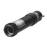
■ Specifications
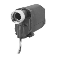
Shielded type proximity sensor (suitable for flush mounting
onto metal)
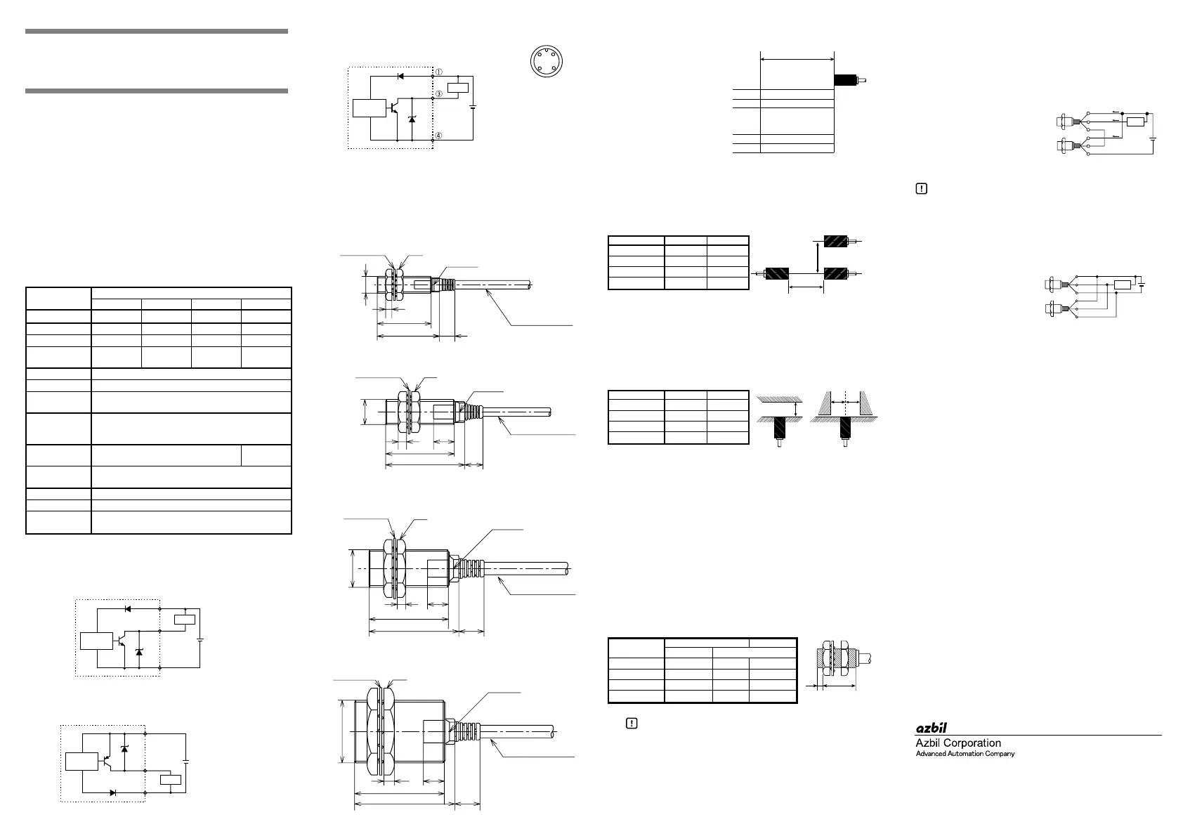
■ Circuit and Wiring
● Pre-wired type (NPN) FL7M-_A/B_
● Pre-wired type (PNP) FL7M-_D/E_
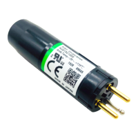
● Pre-wired connector type (NPN)
FL7M-1P5A6-CN03
•A load must be used when power is applied to the sensor.
•A combination of short circuit and wrong wiring will cause
permanent damage, regardless of short-circuit protection.
• When connecting a connector fasten tightly by hand.
■ Dimensions
● FL7M-1P5_6_
● FL7M-2_6_
● FL7M-5_6_
● FL7M-10_6_
■ Operating Chart for Output and Indicator
■ Mutual Interference
Erroneous operation due to mutual interference is caused when
sensors are installed in parallel or facing each other.
Separate the sensors by at least the distance specified in the
table below.
■ Influence from Adjacent Metal
Metals opposite the sensor's sensing face must be removed to
avoid false actuation.
Keep metals away from the sensors as specified below.
Shaded areas indicate surrounding metal other than the target
object.
A : Distance between front of iron plate and sensing face of
proximity sensor.
B : Distance between side of iron plate and center of proximity
sensor sensing face.
■ Tightening Torque
● When a nut is used
The permissible torque is different depending upon the
distance from the top of the sensor head. Tighten the body at
less than the maximum permissible torque shown below,
and always with the enclosed nuts and washers.
The tightening torque varies depending on the mounting
plate or housing, the nut and washer material, and the
condition of the mounting surface. Check that the torque is
suitable for the actual combination of items before use.
Handling Precautions
• Do not tighten the body by applying torque to the
indicator unit (plastic unit).
• Do not mount the body using a setscrew. Doing so
might damage the sensor.
■ AND Connection (Serial Connection)
When connecting two sensors in series, please pay attention to
the following:
• Maximum output current (100mA) ≥ load current + current
consumption (13mA)
• Supply voltage ≥ operation voltage of a load + 2 x voltage
drop (2V)
• If target moves too quickly,
sensor may operate incorrectly.
• In series, sensor A may operate
incorrectly on startup, because
sensor A is supplied power from sensor B's output.
Handling Precautions
• With serial connections the sensor may be briefly
unusable due to power fluctuation. Check the
system before use.
■ OR Connection (Parallel Connection)
Up to three of these sensors may be connected in parallel.
■ Points to be Aware of When Handling
• Do not swing the sensor by the cable.
• Do not pull the cable with excessive force.
• Do not use the sensor outdoors, or where it is surrounded by
chemicals (solvents, acids, alkalies, etc.).
• If bending the cable, keep R (the radius of the bend) ≥ (the
cable diameter) x 3 at least.
• When disposing of an FL7M Series switch, dispose of it
appropriately as industrial waste in accordance with
applicable bylaws and regulations.
■ Wiring cautions
• Route the wires of the sensor separately from power lines or
through an exclusive conduit. Otherwise, electrical noise or a
surge may cause faulty operation or damage.
• If an extension of the cable is necessary, use at least a
0.3mm
2
wire of 100m maximum length.
• When using a commercial switching regulator, ground the
FG (Frame Ground) and G (Ground) terminals. Otherwise,
switching noise may cause faulty operation.
• When using a load to generate a transient current, connect a
current limit resistor between the load and the output
terminal. (Otherwise, the short-circuit protection may be
activated.)
Proximity Sensors FL7M Series
(3-wire DC Type)
User's Manual
CP-UM-5373E
Model number
FL7M-
1P5_6_ 2_6_ 5_6_ 10_6_
Size M8 M12 M18 M30
Sensing distance 1.5mm 2mm 5mm 10mm
Setting distance 0 to 1.05mm 0 to 1.4mm 0 to 3.5mm 0 to 7mm
Standard target
8 x 8 x 1mm 12 x 12 x 1mm18 x 18 x 1mm 30 x 30 x 1mm
(steel)
Hysteresis 10% max. of sensing distance
Supply voltage 10 to 30Vdc
Current
13mA max.
consumption
Output Load current: 100mA max.
Voltage drop: 2V max.
Withstand voltage: 30V max.
Operating
-25 to +70°C -10 to +60°C
temperature
Insulation
50MΩ min. (500Vdc)
resistance
Dielectric strength 1000Vac 1min
Sealing IP67 (IEC Standard)
Circuit protection Surge voltage protection, reverse polarity protection,
short circuit protection
Load
Brown
Black
10 to 30Vdc
Blue
+V
0V
OUT
NPN
10 to 30Vdc
+V
0V
OUT
PNP
Load
Brown
Black
Blue
10 to 30Vdc
+V
0V
OUT
NPN
Load
Connector
face view
12
34
30
26
M8 x 1
3
7
Nut
Indicator
Tooth washer
Vinyl insulated cable
(4 dia. 0.3mm )
2
Unit: mm
M12 x 1
938
33
104
Nut
Indicator
Tooth washer
Vinyl insulated cable
(4 dia. 0.3mm )
2
M18 x 1
1243
38
4 10
Nut
Indicator
Tooth washer
Vinyl insulated cable
(6 dia. 0.5mm )
2
5 10
43
48 12
M30 x 1.5
Nut
Indicator
Tooth washer
(6 dia. 0.5mm )
2
Vinyl insulated cable
OFF
OFF ON
RED OFF
ON OFF
Sensing distance
RED
Proximity
Sensor
Indicator
Output
Indicator
Output
FL7M-_A/D6_
(N.O.)
FL7M-_B/E6_
(N.C.)
B
A
A(mm) B(mm)
FL7M-1P5_6_ 15 20
FL7M-2_6_ 20 30
FL7M-5_6_ 35 50
FL7M-10
_6_ 70 100
B
A
B
A(mm) B(mm)
FL7M-1P5_6_ 4.5 6
FL7M-2_6_ 89
FL7M-5_6_ 20 13.5
FL7M-10
_6_ 40 22.5
Part A Part B
Distance (mm) Permissible torque (N•m)
FL7M-1P5_6_ 9912
FL7M-2_6_ 0-20
FL7M-5_6_ 0-70
FL7M-10
_6_ 0-180
PartBPartA
Load
+
+
-
-
OUT
OUT
i
iL
i
Vs
A
B
OUT
OUT
Vs
Load
+
+
-
-
Specifications are subject to change without notice. (09)
1-12-2 Kawana, Fujisawa
Kanagawa 251-8522 Japan
URL: http://www.azbil.com
1st edition: Sep. 2004 (M)
3rd edition: Aug. 2013 (F)
 Loading...