EasyManua.ls Logo

Azbil FL7M Series User Manual

Azbil FL7M Series
8 pages
To Next Page IconTo Next Page
Page #1 background imageLoading...
Page #1 background image
Name Appearance O.D. Catalog listing
Mounting bracket
Protective cover
Spatter-guarded
protective cover
For M12
For M18
For M30
For M12
For M18
For M30
For M08
For M12
For M18
For M30
FL-PA112
FL-PA118
FL-PA130
FL-PA12
FL-PA18
FL-PA30
FL-PA08W
FL-PA12W
FL-PA18W
FL-PA30W
ORDER GUIDE
Standard (pre-leaded) type (2 m cable)
Connector type
Pre-leaded connector type (30 cm cable)
Accessories (sold separately)
Exterior Sensing distance
Operation
mode
Setting
indicator
Catalog listing
Exterior Sensing distance
Operation
mode
Setting
indicator
Catalog listing
Exterior Sensing distance
Operation
mode
Setting
indicator
Catalog listing
AC/DC2-wire Type Cylindrical
Proximity Switches
No-polarity 2-wire general-purpose switches are easy to use.
2-wire type for both AC and DC greatly reduces wiring man-hours
Stable sensing area displayed by setting indicator (green/red LED)
Indicator lamp can be seen even from the rear
(preleaded and preleaded connector types)
Compact and space-saving
Sealed to IP67
Enhanced circuit protection (surge absorption, load short-circuit)
FL7M
Series
1

Other manuals for Azbil FL7M Series

Question and Answer IconNeed help?

Do you have a question about the Azbil FL7M Series and is the answer not in the manual?

Azbil FL7M Series Specifications

General IconGeneral
Power supply12-24 VDC
Operating temperature-10°C to +50°C
Sensing methodInfrared
Number of beams4
Alarm outputRelay

Summary

ORDER GUIDE

Standard (Pre-leaded) Type

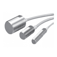
Catalog listing for standard pre-leaded 2m cable proximity switches.

Connector Type

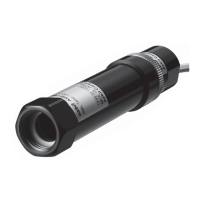
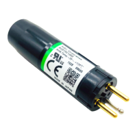
Catalog listing for connector type proximity switches.

Pre-leaded Connector Type (30cm)

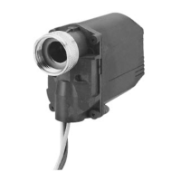
Catalog listing for pre-leaded connector type switches with 30cm cable.

Accessories

List of separately sold accessories like mounting brackets and protective covers.

SPECIFICATIONS

About Setting Indication

Explanation of how the indicator lamp shows sensing status and stable sensing area.

PERFORMANCE CHARACTERISTICS

Sensing Area (typical)

Typical sensing area diagrams showing detection range based on object size and position.

Sensing Distance vs. Material/Size

Charts showing sensing distance variation with target object material and size.

Voltage Drop (typical)

Typical voltage drop characteristics of the proximity switches under different load currents.

Leakage Current (typical)

Typical leakage current characteristics based on supply voltage.

EXTERNAL DIMENSIONS

Standard (Pre-leaded) Type Dimensions

Detailed external dimensions for standard pre-leaded proximity switch models.

Connector Type Dimensions

Detailed external dimensions for connector type proximity switch models.

ACCESSORY DIMENSIONS

Pre-leaded Connector Type Dimensions

Detailed external dimensions for pre-leaded connector type proximity switch models.

Mounting Bracket Specifications

Dimensions and screw sizes for mounting brackets.

Protective Cover Specifications

Dimensions for protective covers compatible with switch external dimensions.

Spatter-Guarded Cover Specs

Dimensions for spatter-guarded protective covers for shielded switches.

WIRING AND CONNECTORS

Wiring Diagrams

Schematic diagrams illustrating wiring for pre-leaded and pre-leaded connector types.

Connector Specifications

Technical specifications for PA5 series connectors used with the switches.

PRECAUTIONS FOR USE (PAGE 7)

Mounting Precautions

Guidelines for proper mounting, including tightening torque and surrounding metal influence.

Mutual Interference Prevention

Recommended distances to prevent interference when mounting switches in parallel or facing each other.

Cable with Connector

Information on using PA5 Series connectors with cables for specific switch types.

FURTHER PRECAUTIONS (PAGE 8)

Series/Parallel Connection Cautions

Advice on series and parallel connection for AND/OR switching circuits.

Load and Operation Considerations

Guidance on handling inrush current loads, power supply connection, and power-on delay.

Cable Bend Radius and Leakage

Information on minimum cable bend radius and influence of leakage current.

Related product manuals