12
AB-6600
•
To wire between the microswitch and the screw terminals, lay the wires from the terminals to the
microswitch though the bottom inside of the box.
•
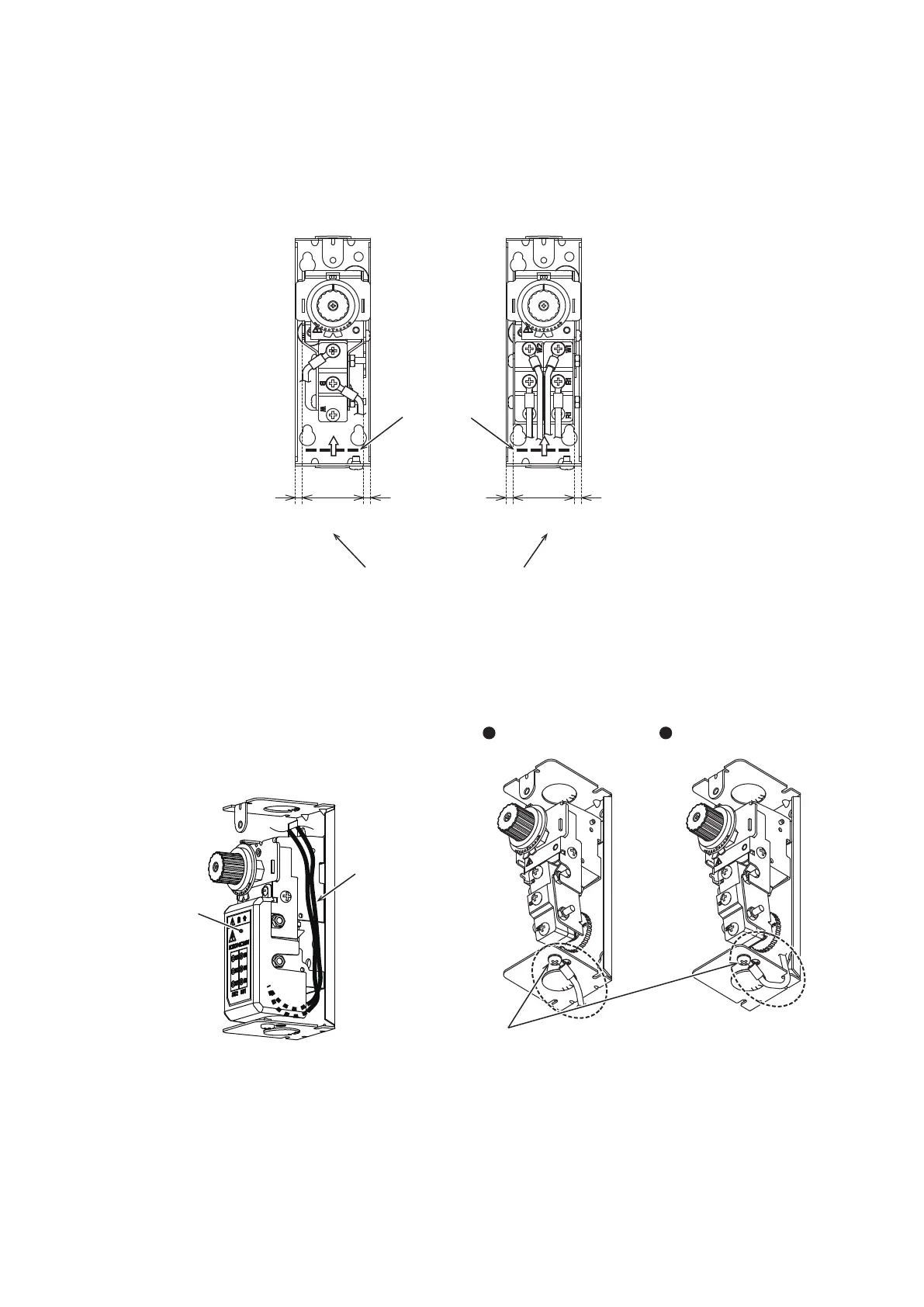
Connect the wires to the screw terminals using the round screw terminals (M4 size) as shown in Figure 19.
Note: If the wiring was done improperly, the terminal lugs or wires may interfere each other and the terminal cover cannot be attached.
Note: Insert the wires through bottom of the terminal cover opening and lay the wires in direction as illustrated by the arrow.
Figure 19.
●Example of TY6800 ●Example of TTY6800
Position of the terminal
cover opening
Approx.
4 mm
(Clearance for wiring)
Approx.
4 mm
(Clearance for wiring)
Approx.
38 mm
Approx.
4 mm
(Clearance for wiring)
Approx.
4 mm
(Clearance for wiring)
Approx.
38 mm
Fit the wires and crimp terminal lugs within this range considering the terminal cover attachment.
•
If the knockout hole on the top of box is used,
lay the wires along the inside wall of the box and
connect the wires to the microswitch form the
bottom side.
z
Example of wiring from the top side of box
Lay the wires along the inside wall of the box and connect the
wires to the microswitch terminals form the bottom side of the
terminal cover. Also the opposite side of the box illustrated in
Figure 20. is applicable.
Figure 20.
Terminal cover
Wires
•
Wire to the ground terminal (earth) as shown in
Figure 21.
Note: Detach the terminal screw and connect the ground
wire using an insulated round crimping terminal (M4
size)..
Note: Common for Model TY6800Z, TTY6800Z.
Figure 21.
Screw for ground terminal
Grounded outside
the case
Grounded by pulling
the cable from the case
 Loading...