15
AB-6600
z
Model TTY6800Z
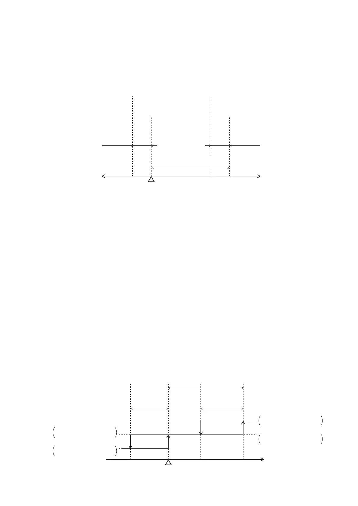
As shown in Figure 27. Setpoint and differential gap for Model TTY6800ZE, the differential gap of each switch
is xed to 3 °C.
A dial for setting the setpoint is placed above the switch 1. Differential between two switches can be set
approx. in 2.5–8 °C range.
Figure 27. Setpoint and differential gap for Model TTY6800Z
< Cooling two-step control >
Based on the cooling control system shown in Figure 17. Example of wiring for cooling two-step control,
two chillers are installed. Operation of Model TTY6800Z thermostat is described assuming the temperature
setpoint: -10 °C, differential gap: 3 °C, differential between two switches: 8 °C.
(1) When the temperature of the controlled target rises to the setpoint (-10 °C), the switch 1 works to close the
terminal R1 and W1, and then the chiller 1 starts.
(2) Along with operation of chiller 1, when the temperature of the controlled target falls to -13 °C, that is
setpoint (-10 °C) minus differential gap (3 °C), the switch 1 works to open the terminal R1 and W1, and
then the chiller 1 stops.
(3) Although the chiller 1 keeps operating, if the temperature of the controlled target keeps rising and it
reaches -2 °C, that is setpoint (-10 °C) plus the differential between two switches (8 °C), the switch 2 works
to close the terminal R2 and W2, and then the chiller 2 starts.
(4) Along with operation of chiller 1 and chiller 2, when the temperature of the controlled target falls to -5 °C,
that is chiller 2 triggered temperature (-2 °C) minus the differential gap (3 °C), and then the chiller 2 stops.
Only the chiller 1 operates.
(5) When temperature of the controlled target falls further to -13 °C, that is setpoint (-10 °C) minus the
differential gap (3 °C), and then the chiller 1 stops.
(6) When the temperature of the controlled target rises again, the steps from (1) will be carried out
automatically.
Figure 28. Example of cooling two-step control
[°C]
Sensor (ambient temp.)
Temperature rise
Sensor (ambient temp.)
Temperature fall
Switch 1
Differential gap
3 °C (fixed)
Switch 2
Differential gap
3 °C (fixed)
Differential between two switches
Approx. 2.5-8 °C (variable)
Differential between two switches
Approx. 2.5-8 °C (variable)
Setpoint
Between terminal R1 and W1: Open
Between terminal R1 and B1: Close
Between terminal R1 and W1: Close
Between terminal R1 and B1: Open
Between terminal R2 and W2: Close
Between terminal R2 and B2: Open
Between terminal R2 and W2: Open
Between terminal R2 and B2: Close
Temperature of sensor [ °C]
-10
(Setpoint)
-2-5-13
(2) (1),(5)
(4) (3)
Chiller 1 ON
Between R1 and W1: Close
Between R1 and B1: Open
Chiller 1 OFF
Between R1 and W1: Open
Between R1 and B1: Close
Chiller 2 ON
Between R2 and W2: Close
Between R2 and B2: Open
Chiller 2 OFF
Between R2 and W2: Open
Between R2 and B2: Close
Switch 2
Differential gap
3 °C
Differential between two switches
8 °C
Switch 1
Differential gap
3 °C
 Loading...