Do you have a question about the b-red AKW200 and is the answer not in the manual?
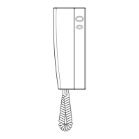
Specifies the dimensions of the handset unit.
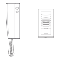
Describes the entry panel's single button, LED indicator, potentiometers, and lock connection capability.
Details on the connections for power supply, data extension, and solenoid lock.
Configures single or second call activation for the entry panel.
Details the 9VA transformer, overload protection, and 18V stabilized output.
Details on 230V mains input and 18V stabilized current output connections.
Explains electronic protection and reset procedure for power supply interruptions.
Instructions for fixing the back plate, mounting, and connecting cables for the handset.
Steps to remove front plate, cable grip, fix back plate, connect, and secure the entry panel.
Guidance on installing the power supply unit on DIN rail or wall-mounted.
Details the functions of the two buttons on the handset for door lock and intercom.
Instructions for making calls between internal units and handling busy signals.
Guidance on how to access and write on the label for the entry panel.
Diagram showing a bifamiliar configuration for two groups with intercom facility.
Table detailing maximum cable distances (La, Lb, Lc) based on wire cross-section.
Diagram illustrating the basic setup for the intercom system.
Diagram showing a configuration for one family with intercom facility.
Explains the function of jumpers JP1, JP2, JP3, and JP4 for calls and volume.
| Brand | b-red |
|---|---|
| Model | AKW200 |
| Category | Intercom System |
| Language | English |