1: OPERATING AREA AND CONDITIONS
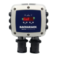
The Bacharach MGS Series controllers provide local
alarm status indicaons (via mul-colored, per-
channel LEDs) as well as common single-level or
dual-level digital (relay) alarm outputs based on 1, 2,
4, or 6 input signals and 1 or 2 user-definable
set-points.
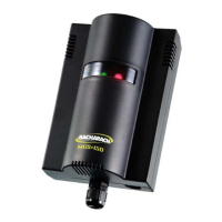
MGS Controllers support mulple input sensors/
transmiers (1, 2, 4, or 6 channels) based on the
model of the controller. Inputs are standard 4-20 mA
signals from MGS-series sensors or any standard,
linear, 4-20 mA transmier.
The instrument is powered 100V-230V AC (50-60Hz) or
12V DC (specified at me of order).
P/N: 6709-9002
Revision 0
January 25, 2016
2: SAFETY INSTRUCTIONS
USER MANUAL: Before using this equipment,
carefully read and strictly follow the User
Manual (part number 6709-9000). The user
must fully understand and strictly observe the
instrucons. Use the equipment only for the
purposes listed and under the condions speci-
fied in those documents.
CODE COMPLIANCE: Comply with all local and
naonal laws, rules and regulaons associated
with this equipment.
GENUINE PARTS: Use only genuine Bacharach
spare parts and accessories, otherwise proper
funconing of the equipment may be impaired.
TECHNICIAN USE ONLY: This unit must be
installed by a suitably qualified technician who
will install this unit in accordance with these
instrucons and the standards in their parcular
industry/country. Operators of the unit should
be aware of the regulaons and standards in
their industry/country for the operaon of this
unit. These notes are only intended as a guide
and the manufacturer bears no responsibility for
the installaon or operaon of this unit.
Failure to install and operate the unit in accor-
dance with these instrucons and with industry
guidelines may cause serious injury including
death and the manufacturer will not be held
responsible in this regard.
SAFE MOUNTING: This controller must be
connected by a marked, suitably located and
easily reached switch or circuit-breaker as
means of disconnecon.
WARNING: Strictly follow the instruc-
ons in the Controller Manual (part
number 6709-9000) available at
www.MyBacharach.com.
CAUTION: DO NOT MOUNT the MGS
Controller in an area that may contain
flammable liquids or vapors. Opera-
on of electrical equipment in such
an area constutes a safety hazard.
World Headquarters
621 Hunt Valley Circle
New Kensington, PA 15068 USA
Phone: 724-334-5000 • Fax: 724-334-5001
Toll Free: 1-800-736-4666
Website: www.MyBacharach.com
E-mail: help@MyBacharach.com
114A Georges Street Lower
Dun Laoghaire • Co Dublin • Ireland
Phone: +353 1 284 6388 • Fax: +353 1 284 6389
INSTALLATION GUIDE
4: DIMENSIONS
ENVIRONMENTAL CONSIDERATIONS: Care-
fully consider the full range of environmental
condions to which the instruments will be
exposed.
APPLICATION CONSIDERATIONS: The specifics
of the applicaon (for example, possible leaks,
air movement/dra, etc.) must be observed.
ACCESSIBILITY CONSIDERATIONS: The degree
of accessibility required for maintenance
purposes must be granted.
ACCESSORY CONSIDERATIONS: The types of
oponal and accessory equipment that will be
used with the system must be kept in mind.
ELECTRONIC CONSIDERATIONS: The system
contains sensive electronic components that
can be easily damaged. Do not touch nor
disturb any of these components.
Mount the MGS Controller according to the
above consideraons, product dimensions (see
Secon 4), and the maximum wiring lengths
(see Secon 5).
3: MOUNTING
Controller Housing
(1-2 Channels)
0.6 in
(15.5 mm)
0.6 in (15.0 mm)
0.5 in (12.7 mm)
2.9 in (74.5 mm)
0.2 in
(4.8 mm)
0.2 in
(5.0 mm)
2.0 in
(50.0 mm)
0.4 in (10.0 mm)
Screw
Screw
0.4 in (9.0 mm)
0.5 in (12.7 mm)
0.6 in
(15.0 mm)
1-2 Sensor
Controller
Housing
O 0.18 in (4.60 mm)
O 0.20 in (5.10 mm)
Mounng
Hole
9.47 in (240.50 mm)
8.85 in (224.70 mm)
10.26 in (260.50mm)
5.13 in (130.25 mm)
9.55 in (242.50 mm)
4-6 Sensor
Controller Housing
Controller Housing
(4-6 Channels)
5: WIRING
1: Strip 0.2 to 0.25 inches (5 to 7 mm)
of wiring insulaon.
2: Connect the wires as indicated.
SHIELD WIRE WARNING: Connect the
shield of the power wires to the earth
ground of the central control system
(e.g., chassis, ground bus bar, etc.).
WARNING: The mains power supply
cable should be of an approved type
based on local regulaons. Connecon
to the mains power supply must be
made via an approved, readily-
accessible, switched and fused plug and
socket (or as per local wiring regula-
ons) which should be within 19 feet (3
meters) of the sesnor/transmier.
CABLE OPENINGS: The metal controller housing
provides a number of PG7 openings for cable glands
or plugs.
NOTE: Aer wiring is completed,
carefully re-assemble the enclosure and
its components.
Refer to the User Manual (part number 6709-
9000) at www.MyBacharach.com for detailed
instrucons on accessing the internal components
for wiring.
Refer to the Controller manual (part
number 6709-9000) at
www.MyBacharach.com for addional
wiring configuraons.