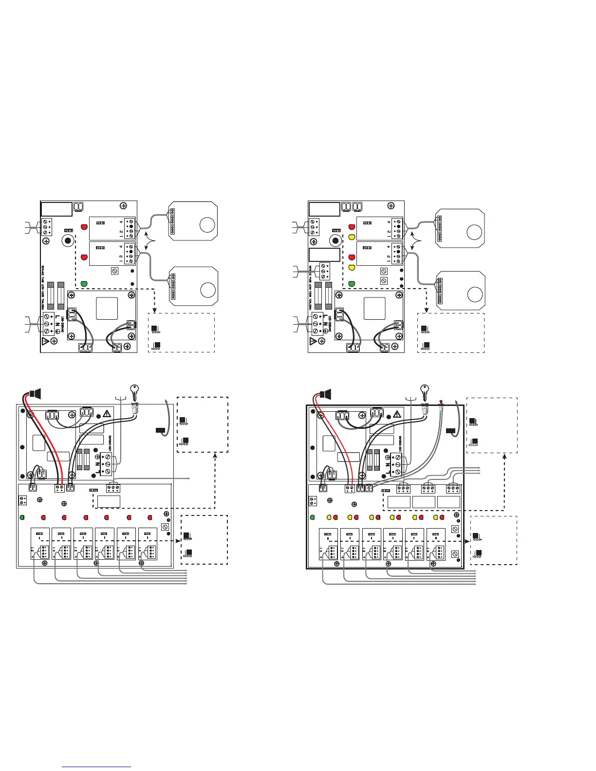
Controller PCB (Alarm Panel)
Alarm
Relay
Mains
Power
Fail Safe Jumper Seng:
OFF
ON
OFF: High Relay Is Energized
On Alarm (Energized on High
Alarm Condion)
ON: High Relay Is Normally
Energized (De-energized on
High Alarm or Mains
Failure Condion)
Transformer
Channel 1
Channel 2
(Oponal)
SENSOR 1
ON OFF
SENSOR 2
ON OFF
FAIL
SAFE
ON
OFF
HIGH
Relay
NC COM NO
MAINS
12V
Fuse 2
Fuse 1
A
u
d
i
b
l
e
A
l
a
r
m
B
u
z
z
e
r
KEY
RED
RED
Chan 1
Alarm LED
Chan 2 Alm
LED (Opt.)
GRN
Sensor Unit
GND
4-20mA OUT
V IN
Sensor Unit
GND
4-20mA OUT
V IN
VHIGH
GND
Controller PCB (Alarm Panel)
High
Alarm
Relay
Fail Safe Jumper Seng:
OFF
ON
OFF: High Relay Is Energized
On Alarm (Energized on High
Alarm Condion)
ON: High Relay Is Normally
Energized (De-energized on
High Alarm or Mains
Failure Condion)
Transformer
Channel 1
Channel 2
(Oponal)
SENSOR 1
ON OFF
SENSOR 2
ON OFF
FAIL
SAFE
ON
OFF
HIGH
Relay 2
NC COM NO
MAINS
12V
Fuse 2
Fuse 1
A
u
d
i
b
l
e
A
l
a
r
m
B
u
z
z
e
r
LOW
Relay 1
NC COM NO
KEY
RESET
RED
RED
YEL
YEL
Chan 1 Alarm LEDs
Chan 2 Alm LEDs (Opt.)
GRN
Low
Alarm
Relay
Mains
Power
VHIGH
VLOW
GND
Sensor Unit
GND
4-20mA OUT
V IN
Sensor Unit
GND
4-20mA OUT
V IN
RED
RED
RED
RED
RED
RED
Chan 1
Alarm LED
Chan 2
Alarm LED
Chan 3
Alarm LED
Chan 4
Alarm LED
Chan 5
Alarm LED
Chan 6
Alarm LED
SENSOR 1 SENSOR 2 SENSOR 3 SENSOR 4 SENSOR 5 SENSOR 6
ON OFF ON OFF
NC COM NO
High Relay
+ 12V -
- SIREN +
PSU
KEY
FAIL SAFE
ON
OFF
To Lid
Ground
Connecon
Base Ground
Connecon
Relay
Output
Fail Safe
Jumper Seng:
OFF
ON
OFF: High Relay Is
Energized On Alarm
(Energized on High
Alarm Condion)
ON: High Relay Is
Normally Energized
(De-energized on
High Alarm or Mains
Failure Condion)
Sensor Enable
Jumper Sengs:
OFF
ON
OFF: Sensor is
disabled for this
channel
ON: Sensor is
enabled for this
channel
Ensure that connecons 1 to 4
on each sensor connect to their
corresponding numbers on the
terminal block in the main
alarm unit, otherwise the
system will not funcon
correctly and could be
damaged.
Fuse
MAINS
12V
50/60Hz
Fuse
REPLACE FUSE
WITH M205
T2AL250V
Mains
Power
Horn
(12 VDC, 200 mA Max)
Key
Switch
VHIGH
GND
ON OFF ON OFF ON OFF ON OFF
GRN
Fuse
MAINS
12V
50/60Hz
Fuse
REPLACE FUSE
WITH M205
T2AL250V
Chan 1
Alarm LEDs
Chan 2
Alarm LEDs
Chan 3
Alarm LEDs
Chan 4
Alarm LEDs
Chan 5
Alarm LEDs
Chan 6
Alarm LEDs
NC COM NO
High Relay Low Relay Fault Relay
NC COM NO
NO COM NC
+ 12V -
- SIREN +
PSU
KEY RESET
To Lid
Ground
Connecon
Base Ground
Connecon
Mains
Power
Horn
(12 VDC, 200 mA Max)
Key
Switch
Push
Buon
Switch
Ensure that connecons 1 to 4
on each sensor connect to their
corresponding numbers on the
terminal block in the main
alarm unit, otherwise the
system will not funcon
correctly and could be
damaged.
Relay
Outputs
Fail Safe
Jumper Seng:
OFF
ON
OFF: High Relay Is
Energized On Alarm
(Energized on High
Alarm Condion)
ON: High Relay Is
Normally Energized
(De-energized on
High Alarm or Mains
Failure Condion)
Sensor Enable
Jumper Sengs:
OFF
ON
OFF: Sensor is
disabled for this
channel
ON: Sensor is
enabled for this
channel
FAIL SAFE
ON
OFF
RED
RED
RED
RED
RED
RED
YEL
YEL
YEL
YEL
YEL
YEL
GRN
SENSOR 1 SENSOR 2 SENSOR 3 SENSOR 4 SENSOR 5 SENSOR 6
ON OFF ON OFF ON OFF ON OFF ON OFF ON OFF
VHIGH
VLOW
GND
2 Sensor 1 Alarm Confirguraon
2 Sensor 2 Alarm Confirguraon
6 Sensor 1 Alarm Confirguraon
6 Sensor 2 Alarm Confirguraon
3-conductor cable (stranded);
500 (152 m) max;
22 AWG; Max 8.8Ω/wire
3-conductor cable (stranded)
(6 places max);
500 (152 m) max; 22 AWG;
Max 8.8Ω/wire
3-conductor cable (stranded)
(6 places max);
500 (152 m) max; 22 AWG;
Max 8.8Ω/wire
3-conductor cable (stranded);
500 (152 m) max;
22 AWG; Max 8.8Ω/wire
 Loading...