Page-4 Instruction 0023-9125
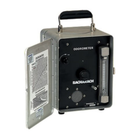
ODOROMETER
1. Make sure batteries are in place (See Appendix A-1 for AC models).
2. The gas supply should be connected to the inlet fi tting on the front
panel, and pressure should be below 5 psig. Connection should be
made with aluminum or plastic tubing only; do not use copper or
rubber, as these tend to remove odorant compounds. A 6 foot length
of suitable plastic tubing is supplied with the instrument.
3. Where possible, tests should be run in an odor and draft free area.
4. Set the instrument on a level bench or desk. Swing the handle down,
and the top cover open. Switch the unit "ON" (Clockwise), the green
POWER LED should light (See Appendix A-2 for older models).
NOTE: If the LED goes out after a few seconds, replace the batteries.
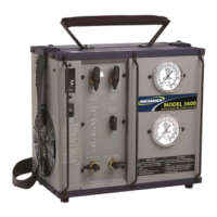
5. The GAS INLET NEEDLE VALVE is located in the center of the
panel. Open the valve slowly while sniffi ng the air being discharged
from the SNIFFER FUNNEL opening in the top of case.
ODOROMETER
3. OPERATING
INSTRUCTIONS
ON
10
8
6
4
2
ODOROMETER
ON - OFF
SWITCH
POWER
LED
GAS INLET
NEEDLE
VALVE
SNIFFING
FUNNEL
FLOWMETER
GAS
INLET
FITTING
AIR
INLET