Do you have a question about the Bacharach PCA3 and is the answer not in the manual?
Provides an overview of the manual's purpose and content.
Explains symbols and formatting used throughout the manual.
Highlights critical safety warnings and precautions for using the analyzer.
Details the PCA®3 analyzer, its components, and intended use.
Provides a high-level summary of how to operate the analyzer.
Lists the key capabilities and advantages of the PCA®3 analyzer.
Outlines different product configurations and their associated model numbers.
Lists the technical specifications, performance, and capabilities of the analyzer.
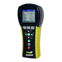
Introduces the hardware components of the PCA®3 analyzer.
Describes the function of each button on the analyzer's front panel.
Explains the features and capabilities of the analyzer's graphic display.
Details the location and type of batteries used in the analyzer.
Describes the AC adapter connection for external power supply.
Identifies and describes the connectors for the probe and hose assembly.
Explains the function and use of the differential pressure port.
Describes the connector for the primary air thermocouple.
Details the USB port for data transfer to a computer.
Explains the IrDA port for wireless printing capabilities.
Describes the connector for optional external measurement features.
Lists essential steps required before configuring or using the analyzer.
Explains the different power options available for the analyzer.
Provides instructions for attaching the probe and hose assembly.
Guides the user on steps needed before configuring the analyzer's settings.
Lists factory default settings and how to change them.
Instructions for selecting the correct fuel for accurate combustion analysis.
Explains how to configure the CO sensor zeroing function.
Allows selection of temperature display units (°C or °F).
Allows selection of pressure display units (e.g., inwc, mb).
Configures the units for displaying pollution measurements.
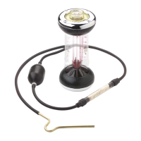
Procedure for entering smoke numbers measured by a separate tester.
Sets whether oil derivatives were present during a smoke test.
Allows manual entry of boiler temperature from an external device.
Sets the analyzer's internal clock for date stamping records.
Sets the analyzer's internal clock for time stamping records.
Sets the O2 reference percentage for gas measurements.
Determines whether pressure measurements are included in printouts.
Allows adjustment of text size on the Run/Hold screen for readability.
Activates and configures automatic data logging functions.
Enables or disables audible feedback for button presses.
Allows manual entry of up to three lines of text for test identification.
Allows manual entry of user or owner information for printouts.
Selects the display language for the analyzer's interface.
Sets a reminder for periodic calibration of the analyzer.
Customizes the order of data displayed on the Run/Hold screen.
Provides advice and best practices for operating the analyzer effectively.
Step-by-step instructions for powering on and initializing the analyzer.
Explains the low battery indicator and its implications.
Guides users on where to position the probe for accurate sampling.
Detailed procedure for conducting a standard combustion test.
Allows users to label pressure measurements for clarity.
Describes how to measure and label temperature differences.
Instructions for measuring draft or differential pressure.
Explains how to save combustion, pressure, or temperature data.
Procedure for safely concluding a combustion test.
Instructions for maintaining the water trap/filter assembly.
Details on how to activate, configure, and use data logging features.
Explains how to manage and recall stored test data.
Guides on transferring stored data to a PC using Fyrite® User Software.
Information on how to import downloaded data into spreadsheet programs.
Instructions for printing test data via IrDA or stored memory.
Procedure for safely shutting down the analyzer and purging sensors.
Introduction to B-Smart® sensor technology and its benefits.
General steps to initiate any calibration procedure.
Procedure for replacing and calibrating B-Smart® sensors.
Detailed procedure for calibrating the pressure sensor.
Procedure for zeroing and spanning the stack temperature channel.
Procedure for zeroing and spanning the ambient air temperature channel.
Procedure for calibrating the COLow sensor, optionally with H2 compensation.
Procedure for spanning the optional Sulfur Dioxide sensor.
Procedure for spanning the optional Nitric Oxide sensor.
Procedure for spanning the optional Nitrogen Dioxide sensor.
Procedure for spanning the optional Carbon Monoxide high sensor.
Outlines the limited customer maintenance tasks for the analyzer.
Provides a step-by-step guide for disassembling the analyzer.
Instructions for emptying the water trap chamber after use.
Procedure for replacing the filter element in the water trap.
Detailed instructions for replacing various gas sensors.
Procedure for replacing the bias battery for the NO sensor.
Instructions for cleaning the probe tube and gas sample hose.
Explains the meaning of error symbols displayed on the analyzer.
Describes how to access and interpret diagnostic and status information.
Guide to navigating and using the analyzer's diagnostic menu.
Guide to accessing the status screen for quick reference.
Lists common error messages and suggested remedies after warm-up.
Lists part numbers for common replacement components.
Lists optional and standard accessories available for the analyzer.
Information on recommended field repair procedures and limitations.
Contact information for authorized service centers in the US and Canada.
| Type | Combustion Analyzer |
|---|---|
| Gases Measured | O2, CO, NO, NO2, SO2 |
| O2 Range | 0 to 25% |
| Sensor Type | Electrochemical |
| Display | Backlit LCD |
| Connectivity | Bluetooth |
| Power | Rechargeable Li-ion battery |