Do you have a question about the BAFANG MM G510.750.C and is the answer not in the manual?
Lists the available product models for the M620 series.
Defines the applicability of the pedelec motor for road use, excluding sport competitions.
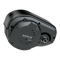
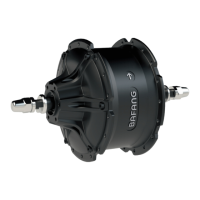
Details the graphic representation of product identification numbers shown on the housing.
Provides detailed dimensions and geometric measurements of the motor unit.
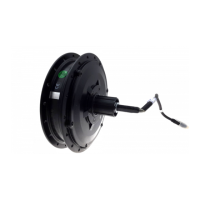
Describes the surface treatment of the motor, specifying a shockproof black coating.
Advises on proper storage conditions, recommending a ventilated dry room away from magnetic objects.
Lists the necessary tools for performing the drive unit installation, including hex wrenches and spanners.
Details the steps for mounting the motor onto the bicycle frame, including bolt insertion.
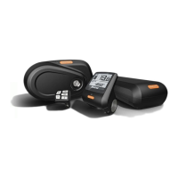
Explains how to connect various cables, including battery, speed sensor, EB-BUS, and lights.
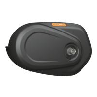
Describes the process of fastening the motor cover using specific screws and torque.
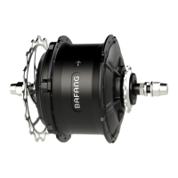
Outlines the steps for installing the chain wheel onto the spline shaft and tightening the lock nut.
Details the procedure for mounting the crank onto the axle and tightening the hexagon screws.
Guides the installation of the external speed sensor and its magnet onto the bicycle.
| Motor Type | Mid Drive Motor |
|---|---|
| Rated Power | 750W |
| Voltage | 48V |
| Brake Type | Disc Brake Compatible |
| IP Rating | IP65 |
| Wheel Size | 26", 27.5", 29" |
| Max Torque | 120 N.m |