Do you have a question about the BAFANG MAX Drive System and is the answer not in the manual?
Essential guidelines for professional use and safety precautions.
Key safety information for the end-user regarding e-bike operation.
Guidelines for safe installation and maintenance procedures.
Crucial operational and safety notes for product users.
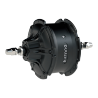
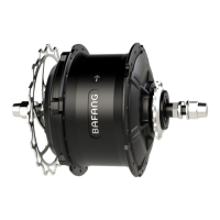
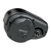
Key features and benefits of the drive unit.
Environmental conditions for proper drive unit operation.
Explanation of the product's naming conventions and codes.
Detailed technical specifications of the drive unit.
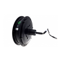
Diagrams and measurements of the drive unit's physical structure.
List of necessary tools for system installation.
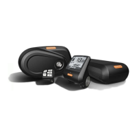
Identification of all components within the drive system.
Step-by-step guide for mounting the display unit.
Instructions for installing the auxiliary keypad.
Procedure for installing the battery mounting rail.
Guide for installing the external speed sensor.
Procedure for mounting the drive unit onto the bike frame.
Connecting the battery power and communication cables to the drive unit.
Linking the speed sensor cable to the drive unit.
Connecting the EB-BUS cable to the drive unit.
Connecting the headlight cable to the drive unit.
Connecting the headlight cable to the drive unit.
Mounting the front chainwheel without a chain guard.
Procedure for installing a full chain guard.
Installing the crank with a chain guard.
Important precautions for battery handling and usage.
Critical dangers and warnings related to battery use.
Guidelines for correct battery charging and usage.
Instructions and tips for charging the battery.
Procedure for securely installing the battery into its mount.
Technical specifications and operating parameters of the display unit.
Visual representation and physical dimensions of the display.
Overview of display functions and definitions of keys.
Overview of the display's capabilities and communication protocol.
Explanation of the different areas and information displayed.
Identifies and defines the function of each control key.
Basic procedures for operating the display unit.
Controlling the display and vehicle lights.
Activating the walk assistance mode.
Understanding the battery level and status indicators.
Overview of adjustable parameters for the display.
Steps to enter and navigate the parameter setting menu.
How to reset trip data and temporary measurements.
Setting the unit of measurement for distance and speed.
Adjusting the automatic backlight sensitivity.
Adjusting the brightness level of the display backlight.
Setting the automatic display shutdown timer.
Configuring maintenance reminders based on usage.
Setting or changing the display unit's password.
Selecting the correct wheel diameter for accurate speed readings.
Setting the maximum speed limit for the e-bike.
Checking battery communication status with the controller.
Details about battery information displayed in the menu.
List of error codes and troubleshooting methods for display faults.
List of accessories for the display unit.
Detailed list of display unit accessories with part numbers.
List of accessories for the drive unit.
List of drive unit accessories with part numbers.
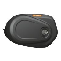
Accessories related to the motor cover.
Components for chain guard assembly.
Details of chain wheel modules.
List of crank components.
List of various cables included in the system.
Details on warranty duration and what is covered.
List of conditions not covered under the warranty.