2
DEALER MANUAL MAX DRIVE SYSTEM
CONTENT
Important Notice 4
For your Safety 5
Note 6
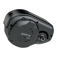
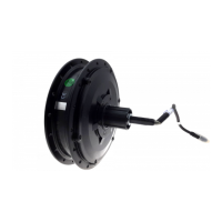
1 Drive Unit (MM G33.350) 7
1.1 Advantages 7
1.2 Scope of Application 7
1.3 Product Naming Protocol 7
1.4 Main Technical Parameters 8
1.5 Drive Unit Structure and Dimensions 9
2 System Installation 10
2.1 List of Tools to be used 10
2.2 Component Names 11
2.3 Display Installation (DP C01.RS232.7) 12
2.4 Auxiliary Keypad Installation 13
2.5 Battery Rail Installation 15
2.6 External Speed Sensor Installation SR SD02.01 15
2.7 Drive Unit Installation 18
3 System Cabling 25
3.1 Connection of the Battery Cable to the Drive Unit 25
3.2 Connection of the Speed Sensor to the Drive Unit 25
3.3 Connection of the EB-BUS to the Drive Unit 26
3.4 Connection of the Headlight Cable to the Drive Unit 26
3.5 Connection of the Headlight to the Drive Unit 27
4 Chain guard Installation 28
4.1 Installation of the Front Chainwheel 28
4.2 Chain Guard Installation (optional) 30
4.3 Crank Installation 37
5 Battery (BT C01.690) 39
5.1 Using the Battery Properly 40
5.2 Charging the Battery 40
5.3 Battery Capacity Display 41
5.4 Battery Health Indication 41
5.5 Battery Installation 42
6 Display (DP C01.RS232.7) 43
6.1 Specifications and Parameters of the Display 43
6.2 Appearance and Dimensions 43
6.3 Function Overview and Key Definitions 44
6.4 Normal Operation 46
6.5 Parameter Setting 48
6.6 Error Code Definitions 55
7 List of Materials 56
7.1 Display Unit - DP C01.RS232.7 56
7.2 Drive Unit - MM G33.350 56
7.3 Cables 58
8 Service and Warranty Policy 59
Notes 60
CONTENT