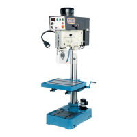
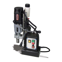
This document describes the Baileigh Industrial DP-1250VS Variable Speed Drill Press, a robust machine designed for drilling and tapping operations in various materials. It emphasizes safe and efficient use, providing detailed instructions for installation, operation, and maintenance.
Function Description
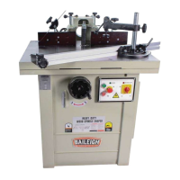
The Baileigh Industrial DP-1250VS is a variable speed drill press primarily used for drilling and tapping. Its variable speed control allows for optimal performance across a wide range of materials and applications. The machine is designed for industrial use, offering precision and durability for demanding tasks.
Important Technical Specifications
The DP-1250VS operates on a 220V, 1Ph, 60Hz power input, utilizing a TEFC Induction motor. It has a 2HP (1.5kw) motor with a speed of 1720rpm. Starting amps are 9.2A, and running amps (no load) are 1.7A. The machine incorporates an M-Type inverter and uses a 14awg, 6 Ft power cable. A 1/8HP, 220V 1ph, 60Hz, 0.4A coolant pump is included.
Capacities:
- Drilling Capacity, Cast Iron: 1.25" (31.75mm)
- Drilling Capacity, Mild Steel: 1" (25.4mm)
- Tapping Capacity, Cast Iron: .75" (19.05mm)
- Tapping Capacity, Mild Steel: .625" (15.875mm)
- Spindle to Table Maximum Distance: 36.41" (925mm)
- Spindle to Base Maximum Distance: 48.22" (1225mm)
- Spindle to Column Maximum Distance: 10.4375" (265.1mm)
- Coolant Capacity: 2 Gal. (7.5L)
Spindle:
- Spindle Taper: MT-4
- Spindle Speed, Low Range: Variable, 85 – 540 rpm
- Spindle Speed, High Range: Variable, 245 – 2000 rpm
- Spindle Travel: 5.9" (150mm)
- Rotation: Fwd/Rev (Rev = Tapping Only)
Table and Column:
- Table Size: 22" x 18.75" (559 x 476mm)
- Table Working Surface: 18.125" x 14.25" (460 x 375mm)
- Table Travel: 15" (381mm) (Without Rack Adjustment)
- Maximum Travel with Rack Adjustment: 20" (508mm)
- T-Slot Number: 2
- T-Slot Size: .625" [5/8"] (15.857mm)
- T-Slot Centers: 7.4375" (188.1mm)
- Table Weight Capacity: 154lbs (70kg)
- Column Diameter: 4.52" (115mm)
Base:
- Base Size: 27" x 19" (686 x 483mm)
- Base Working Surface: 14-3/4 x 11-13/16 In. (375 x 300mm)
- T-Slot Number: 2
- T-Slot Size: .625" [5/8"] (15.857mm)
Main Materials:
- Head: Cast Iron, Steel Cover
- Table and Base: Cast Iron
- Spindle and Quill: Steel
- Column: Steel
Dimensions and Weights:
- Assembled Machine Dimensions (L x W x H): 30.3" x 26.5" x 71.4" (973 x 673 x 1814mm)
- Shipping Crate Dimensions (L x W x H): 60" x 44" x 82" (1524 x 1118 x 2083mm)
- Net Weight: 686lbs (311kg)
- Shipping Weight: 847lbs (385kg)
Usage Features
The DP-1250VS is designed for ease of use and safety. Key features include:
- Variable Speed Control: Allows the operator to adjust spindle speed to match the material and drill bit size, optimizing drilling performance and tool life.
- Digital Indicator: Displays the rate of spindle rotation in RPM, providing precise control.
- Down-Feed Handle: Used by the operator to move the quill down and up.
- Adjustable Table: The worktable can be positioned at varying heights and rotated 180° in either direction. It features T-slots for clamping workpieces.
- Gear Rack: Engages the table for height adjustment.
- Work Light: Provides adequate lighting for the work area.
- Depth Scale Lock: Locks the position of the depth scale for consistent drilling depths.
- Coolant Shut-Off Valve: Controls the volume of coolant, which is crucial for drilling certain materials and extending tool life.
- Emergency Stop Button: Immediately stops all machine functions in an emergency.
- Safety Guard: An adjustable guard with a limit switch ensures safe operation, preventing the machine from running if the guard is not in place.
- Reversible Spindle Rotation: Essential for tapping operations.
Installation and Setup:
- The machine requires a level, concrete floor for installation.
- Proper anchoring to the floor is necessary for stability and safety, using bolts and expansion plugs.
- The power supply should be located close to the machine to avoid tripping hazards.
- Adjusting the Machine Head Height: Involves unlocking the table by turning the crankshaft, placing wood under the head, raising the table, loosening set screws, and then safely securing the head.
- Adjusting the Gear Rack Height: Involves locking the table, unlocking the column bearing, raising the gear rack, and then locking the column bearing.
Operation:
- Drilling: Involves loading and securing the workpiece, securing the drill bit in the chuck, unlocking and adjusting the table, adjusting the safety guard, and selecting the transmission mode. The drilling depth is set using the depth scale indicator.
- Tapping: Similar to drilling, but requires selecting the tapping position on the selector switch and using the reverse button (AD) to reverse the spindle rotation after reaching the desired depth.
- Removing Tooling: Involves disconnecting power, placing wood on the table for protection, positioning the worktable under the spindle, and using a drift key to tap out the bit or chuck arbor.
Drilling Recommendations:
- Drilling Speeds (SFM): The manual provides a comprehensive table of recommended drilling speeds (SFPM) for various materials, including alloy steel, stainless steel, cast iron, aluminum, magnesium, slate, plastics, wood, and titanium alloys.
- Drilling Feed: A table is provided for feed per revolution (inches) based on drill diameter (under 1/8, 1/8 to 1/4, 1/4 to 1/2, 1/2 to 5/8).
- Excessive Speed/Feed Indicators: Warns against a drill that splits up the web, a rapid wearing away of the outer corners of cutting edges, and chipping out at the cutting edges.
Maintenance Features
Regular maintenance is crucial for the longevity and safe operation of the DP-1250VS.
- Daily Maintenance: Includes checking for unsafe conditions, tightening nuts and bolts, cleaning dust and metal chips, checking coolant reservoir levels, cleaning the filter screen, and ensuring the guard and emergency stop are in good working order.
- Weekly Maintenance: Involves checking the oil fill window, thoroughly cleaning the machine and coolant tank, cleaning the machine and area around it, lubricating threaded components and sliding devices, applying rust inhibitive lubricant, and cleaning and greasing the sliding surfaces.
- Monthly Maintenance: Includes checking all screws on the motor, pump, and guard, and ensuring the guard is operating properly. It also specifies greasing the fitting on the side of the drill head pivot for lubricating the gear shaft.
Specific Maintenance Procedures:
- Return Spring: Instructions are provided for adjusting the spindle return spring tension.
- Replacing Gearbox Oil: Detailed steps for draining old oil, cleaning the plug, and refilling with fresh SAE 80W-90 gear oil. This should be done after initial operation, after one month, and every 12 months thereafter.
- Oil Disposal: Emphasizes proper disposal of used oil according to local regulations.
- Greasing the Machine: Instructions for greasing the gear rack on the column and lubricating the spline of the spindle and the teeth of the quill.
- Accessing and Cleaning the Coolant System: Steps for cleaning the drain screen, draining and washing out dirt from the reservoir, replacing the drain plug, thoroughly cleaning the pump and pump inlet, and refilling with coolant solution.
- Oils for Lubricating Coolant: Recommends Baileigh B-Cool 20:1 (water to coolant) biodegradable metal cutting fluid.
- Storing Machine for Extended Period of Time: Instructions for inactivating the drill press, disconnecting electrical supply, emptying and cleaning the coolant reservoir, cleaning and greasing the machine, and covering it.
- Motor / Drive Belt Replacement: Detailed steps for disconnecting power, loosening the set screw, removing high/low shift lever, removing screws and covers, disconnecting wiring, removing the old belt, installing a new belt, and verifying correct operation.
Troubleshooting:
The manual includes a comprehensive troubleshooting section for common issues:
- Faults: Addresses wrong voltage, emergency stop activation, electrical enclosure door malfunction, safety guard malfunction, and limit switch fault.
- Drill Press Does Not Run: Provides remedies for the above faults.
- Excessive Vibration: Suggests checking belt tension, belt wear, and motor/spindle pulley balance.
- Motor Stalls: Recommends checking feed rate, sharpening the drill, and repairing the motor.
- Noisy Operation: Advises lubricating the spline and checking motor bearings.
- Drill or Tool Heats up or Burns Work: Suggests reducing speed, clearing chips, and using pecking operation.
- Drill Leads Off: Recommends sharpening the tool, increasing feed, using cutting oil/coolant, centering the punch/drill, regrinding the drill, tightening the quill, and checking bearings.
- Excessive Drill Runout or Wobble: Advises replacing the drill bit or tool, checking bearing play, and ensuring the drill is seated properly in the chuck.
- Work or Fixture Comes Loose or Spins: Suggests clamping the workpiece or work holding device to the table surface.
Troubleshooting the Inverter:
- Provides guidance for addressing issues related to the electronic component, emphasizing that qualified personnel should perform these tasks.
- Includes a table of error codes and their descriptions, along with corresponding solutions, such as checking motor voltage, input voltage, cooling device, motor overload, grounding, and internal EEPROM.
This drill press is designed to be a reliable and versatile tool for various metalworking applications, with a strong emphasis on user safety and proper maintenance.