Do you have a question about the Baker Hughes Panametrics oxy.IQ and is the answer not in the manual?
Overview of the oxy.IQ Panametrics Oxygen Transmitter.
Information on certifications for hazardous location installations.
Lists typical applications for the oxy.IQ transmitter.
Details the key features and benefits of the oxy.IQ transmitter.
Information on sample handling systems and interference gases.
Instructions for mounting the oxy.IQ unit into the process or sample system.
Detailed steps for connecting the oxy.IQ transmitter wiring.
Step-by-step guide for installing or replacing the oxygen sensor.
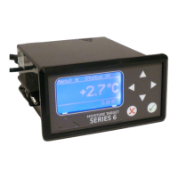
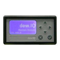
Explanation of the front panel components and their functions.
Overview of the user program menu structure and navigation.
Steps to choose the desired measurement range for the output.
Procedure to calibrate the 4-20 mA analog output endpoints.
Procedure for calibrating the sensor using ambient air.
Procedure for calibrating the sensor using a span gas.
Overview of user programming options without a passcode.
Details on programming calibration settings.
Options for configuring the display settings.
Options for configuring the analog output.
Information on accessing the service menu and its passcode.
Steps to gain access to the service menu.
How to access and view diagnostic information.
Power requirements, cable, and output specs for IS installs.
Power requirements and cable specs for non-incendive installs.
General specifications applicable to all installation types.
Materials in contact with the process stream.
Available ranges for ppm and percent oxygen sensors.
Accuracy specifications for the sensor.
Repeatability specifications for the sensor.
Resolution specifications for the sensor.
Linearity specifications for the sensor.
Operating temperature range for the O2 sensor.
Specifications for sample pressure.
Effect of atmospheric pressure on readings.
Details of the process connection type.
Physical dimensions of the oxy.IQ unit.
Weight of the oxy.IQ unit.
Recommended sample flow rate.
Electrical classification for hazardous locations.
Information regarding European compliance.
Recommended storage conditions for the unit.
Description of the product label markings.
Diagrams showing the physical outline and installation of the oxy.IQ.
Drawings detailing the standard and intrinsically safe cables for the oxy.IQ.
Diagrams illustrating different wiring configurations for the oxy.IQ.
Technical schematic diagram of the oxy.IQ system.
Visual representation of the oxy.IQ user menu structure and navigation.
Visual representation of the service menu structure for qualified personnel.
Details the codes and options for ordering the oxy.IQ transmitter.
Mandatory requirements that must be met when installing the apparatus.
Specific conditions to ensure safe operation and installation of the product.
Information on markings that appear on the oxy.IQ for intrinsically safe versions.
Nominal operating parameters for the device.
Table listing chemical compatibility for different oxy.IQ sensor models.
Table showing O2 concentration ranges for various cell models.
Procedure for returning instruments under warranty or for repair.
| Enclosure Rating | IP65 |
|---|---|
| Measurement Range | 0-100% oxygen |
| Response Time | <10 seconds for 90% response |
| Operating Temperature | -20°C to +50°C (-4°F to +122°F) |
| Operating Humidity | 0-95% RH non-condensing |
| Power Supply | 12-28 VDC |
| Outputs | 4-20 mA, RS485 Modbus |
| Sample Flow Rate | 0.5 to 5 L/min |
| Calibration | Automatic or manual calibration with zero and span gases |