UP
UP
(2)
Emergency Egress Handleset Installation Instructions
Fits 1-3/4" (44 mm) up to 2" (51 mm) doors
(Thick door service kits for doors between
2" (51 mm) up to 2-1/2" (64 mm)
available through customer service)
www.baldwinhardware.com • Customer Service 1.800.437.7448
68595-001 Rev 04
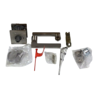
Interior
mounting plate
Interior
escutcheon
Lever
Sleeve
Knob or
Lever
Latches
Exterior handleset
assembly
66199
4697746970 46973
Keys
46967
66209 47031 47063
Parts in the Box
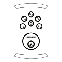
1. Adjust and install latches
2. Install exterior assembly
3. Adjust interior cartridge handing toggle (if needed)
5. Secure bottom screws on interior cartridge and install
knob or lever sleeve
4. Install interior cartridge and cylinder with top screws
6. Check for binding
7. Install interior trim
8. Install knob or lever
9. Install strikes
Troubleshooting
Deadbolt Latch
MEASURE
Latch Face Assembly
For Drive-in Latch
Latch Installation
Latch Assembly and Installation
For Square /
Round Corner
For Square /
Round Corner
For Drive-In Latch
For Drive-In Latch
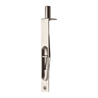
Handleset Latch
Measure your door and prepare using template if needed.
Install exterior assembly and secure by lightly tightening throughbolt.
With a at-blade screwdriver, turn
the (1) handing toggle so that it
points toward the latch bolt. Then
turn the (2) upper cam so that it
points up.
Fully tighten the bottom screws then
fully tighten top screws. Next, install
the knob or lever sleeve.
DO NOT overtighten screws.
BEFORE installing the cylinder, ensure
that the cylinder torque blade is rotated to
align with the D-shaped hole AND that the
upper cam is pointing up on the cartridge.
Install the cylinder and ensure that the torque
blade goes through the D-shaped hole in the latch.
Next, install the cartridge and secure with two
larger screws. Tighten screws evenly.
DO NOT fully tighten screws at this time.
Temporarily place the knob/
lever on the sleeve and turn it to
check for binding.
If the knob/lever does not turn
smoothly, slightly loosen the
mounting screws and repeat
the process until the knob/lever
turns smoothly. Then remove the
knob/lever.
Place the interior trim over the interior cartridge,
ensuring that the spindle is aligned with the
D-shaped hole.
Turn the turnpiece to ensure that the deadbolt
extends smoothly then secure with screws. If it
does not extend smoothly, remove the trim and
slightly loosen the
mounting screws
then test again
until it operates
smoothly.
Rotate the turnpiece to
align spindle with the
D-shaped hole.
mounting screws
sleeve
Place knob/lever onto the
sleeve and turn the set
screw clockwise to secure.
To remove the knob/lever sleeve, use a at-
blade screwdriver to press up on the release.
If backset of door
measures 2-3/4”
(70 mm), adjust
latch by rotating
face as shown.
If backset of door measures 2-3/4”
(70 mm), adjust latch shown by
grasping the spring pin and moving
it to the 2-3/4” slot.
Pin
5-1/2”
(140 mm)
2-3/4” (70 mm)
Remove backplate.
Ensure the latch is inserted with the
word “UP” on top.
Install faceplate with 46977 screws.
Install faceplate with 46970 screws.
Snap together front
and backplate.
tabs
Make sure the slant of latch bolt
faces in the direction that the
door closes.
OR
OR
Snap on collar.
Snap on collar.
Note for 1-1/2” (38 mm) diameter
hole, test if latch extends and retracts.
Chisel out area if required.
Drive in with
hammer.
Drive in with
hammer.
spindle
See drilling template for hole location.
Make sure the curve
of half round spindle
corresponds to the
opening in the latch;
if it does not, reverse
the handing as follows:
(1) Pull spindle away
from mechanism,
(2) rotate it 1/2 turn
180° and release.
Please note: Product illustrations may differ
from your product. Installation is the same.
Rounded edge of
spindle faces latch.
Use two smaller screws
from screw pack 66209
47031
47063
66199
(2x)
Use two larger
screws from screw
pack 66209
46967 (4x)
46973 (2x)
1/8" (3 mm)
pilot holes may
be required.
Depth equal to
screw length.
Longer screws should
be installed closest to
the door jamb.
door jamb
latch bolt
(1)
handing
toggle
(2)
upper
cam
Adjust tang as needed.
Tighten screws
evenly.
DO NOT
overtighten
screws.
The set screws are
pre-installed. They SHOULD
NOT be removed prior
to knob/lever installation.
WARNING: This Manufacturer advises that no lock can provide complete security by itself. This lock may be defeated by forcible or technical means, or evaded by entry elsewhere on the property. No lock can substitute for caution, awareness of your
environment, and common sense. Builder’s hardware is available in multiple performance grades to suit the application. In order to enhance security and reduce risk, you should consult a qualied locksmith or other security professional.
OR
OR
Only use if included in
the box. Not used with
SmartKey products.