Do you have a question about the Baldwin 8252 Series and is the answer not in the manual?
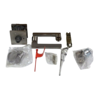
Determine door backset and adjust latch for 2-3/8" or 2-3/4" backset.
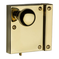
Install strike plate, dust box, reinforcing strike, and associated screws.
Slide the interior cover up and off the main assembly.
Lift the battery case up and out from the interior assembly.
Rotate the turnpiece to a horizontal position for installation.
Place the adapter on the door as shown in the illustration.
Insert cylinder into exterior assembly, ensuring torque blade is vertical.
Mount assembly on door, routing wire harness through adapter and under latch.
Feed wire harness connector through the center hole of the mounting plate.
Tuck wire harness into the notch hole for a flush mounting plate fit.
Ensure exterior assembly is flush, cylinder logo horizontal, then tighten mounting bolts.
Verify the vertical alignment between the mounting plate and exterior assembly.
Test bolt action by retracting and extending with the key for smooth operation.
Align connector with interior assembly port, matching notch to slot.
View alignment from top and push connector firmly to complete connection.
Ensure wires are clear, route harness, and place interior assembly, aligning torque blade.
Once flush, insert and tighten small screws to secure assembly to the mounting plate.
Install 4 new AA alkaline batteries into the pack, ensuring they lie flat.
Mechanism automatically determines door handing and sets motor rotation direction.
Hold LOCK button while inserting battery pack until 2 beeps are heard.
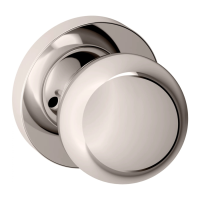
Check that the turnpiece operates correctly (vertical unlocked, horizontal locked).
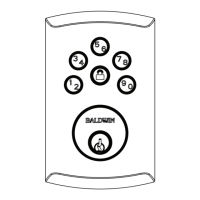
Press program button, enter 4-8 digit code, then press LOCK to save.
Press program button twice, enter 4-8 digit code, press LOCK to save.
Test codes by extending bolt with LOCK button and re-entering code to unlock.
Configure Status LED blinking and lock status color indicators.
Enable or disable the automatic relock feature after 30 seconds.
Enable or disable audible beeps and keypad light feedback.
This switch is designated for future use and has no current function.
Details interior LED, exterior keypad, and audio indicators for low battery status.
Explains keypad backlight activation and various light signals for different events.
Re-run Bolt Direction routine for manual operation issues.
Resynchronize lock by door alignment and re-initiating lock/unlock commands.
Alkaline batteries last over a year; use non-rechargeable for best performance.
Re-initialize lock by removing battery, pressing program button, and reinserting pack.
Set Status LED (SW1) and Auto-lock (SW2) to OFF for maximum battery efficiency.
| Brand | Baldwin |
|---|---|
| Model | 8252 Series |
| Category | Door locks |
| Language | English |