OPERATING INSTRUCTIONS
3-1. INTRODUCTION
This section contains instructions and information
required for the operation
of
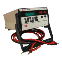
the Ballantine 3440
Series
of
RF
Millivoltmeters. Included are
identification
of
controls, connectors, options and
indicators as well as turn on procedures and
operating instructions.
3-2. CONTROLS, INDICATORS
AND
CONNECTORS
The instrument controls, indicators, and
connectors are described in Table 3-
I.
3-3. METER MECHANICAL ZERO
ADruSTMENT
The mechanical meter zero adjustment
is
a
screwdriver adjustment located
in
the center
of
the
meter
just
below the scale.
If
the meter pointer
does not indicate zero after the voltmeter power
has been
off
for a minute or longer, mechanically
zero the meter as indicated below:
a.
The meter mechanical adjustment screw
is
located centrally on the meter and below the scale.
Rotate the screw CLOCKWISE until the meter
pointer
is
to the left
of
zero
on
the voltage scale
and moving upscale toward zero. Be sure the
instrument
is
in
its normal operating position.
b.
Continue to turn the adjustment screw
clockwise and STOP when the meter pointer
is
precisely on the zero mark.
If
the meter needle
goes beyond zero, repeat step
a.
c.
When the meter pointer
is
precisely over
the zero mark, turn the adjustment screw slightly
counterclockwise to back
off
the tension on the
meter taut-band
suspension.
If
the pointer moves
to the left, repeat
all the above steps, but use less
counterclockwise rotation.
3-4. POWER
Rl~QUIREMENTS
a.
AC Line Voltage Power.
If
ac line voltage
power
is
used, be sure that the Voltage Selector
Switch on the rear panel
is
in
the correct position.
CAUTION: Failure to have the
Voltage Selector Switch in the correct
position can cause serious damage to
your
instrument
and
may
void
the
warranty.
Section
3.
Operating Instructions
b.
Turn the POWER toggle switch to ON and
note that the pilot lamp lights.
WARNING: Be sure to connect the
case
of
the instrument to earth ground
through the power cable or faulty
measurements
and
possible shock
hazard may result.
c.
Internal Battery (Option 05).
If
the optional
rechargeable NiCad battery pack
is
installed
in
the
instrument, simply turn the POWER toggle switch
to ON and note that the pilot lamp lights when
power
is
applied.
NOTE: The pilot lamp serves as a
battery charge indicator.
If
it glows
dimly or does not light when the
POWER toggle switch is turned to
ON,
providing the
power
cord is
disconnected, it indicates that the
battery
is
discharged.
d.
To recharge the battery, (which should
always
be
done after shipment or storage) power
the instrument from the ac line and set the
POWER switch
on
the front panel to the BAT.
CHGE. position. Allow
16
hours to fully recharge
a discharged battery.
e.
A fully charged battery will power the
instrument for over 8 hours. The 3440A cannot be
used for measurements while
in
the BAT. CHGE.
position. Although, with the battery fully
discharged, it can still be operated from the ac line
without any degradation
of
accuracy. When
powered from the ac line, the battery will receive a
trickle charge to keep it
in
a fully charged state.
If
the need should arise, the 3440A may be operated
with the battery removed.
CA
UTION: The internal battery
should not be charged continuously or
its life may be shortened.
Avoid
charging
for
more than
20
continuous
hours.
page 3-1
N8AUM
 Loading...