Do you have a question about the Ballantine 3440A and is the answer not in the manual?
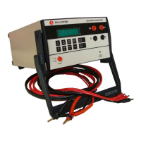
Provides an overview of the Model 3440A RF Millivoltmeter, its features, and accessories.
Details the technical specifications, including frequency range, response, and accuracy.
Specifies the maximum permissible ratio of peak to RMS value of voltage.
Details the maximum uncertainty due to frequency and temperature effects.
Describes accuracy deviations based on ambient temperature and probe heater settings.
Describes the analog meter, scales, and dBm reference.
Specifies the meter pointer unrest for the 1 mV FS range.
Details meter response times and recovery from overload conditions.
Describes the detachable RF detector probe and its connector.
Provides typical input impedance values at specified temperatures.
Lists shunt capacitance values for different voltage ranges.
Specifies VSWR limits for the probe with a non-loading 'T' connector.
Defines the maximum input power required at a specific voltage.
Specifies the probe's protection limits against over voltage.
Describes the rear panel banana jacks for DC output.
Details the probe null balance control for meter zero adjustment.
Explains the REL REF control for sensitivity adjustment and relative readings.
Describes meter response times and the NORMAL/SLOW switch.
Lists operating and storage temperature, humidity, and altitude limits.
Specifies compliance with safety standards.
Details AC operating voltage ranges and internal battery specifications.
Provides the physical dimensions and weight of the instrument.
Details specifications for Option 40 using the 34403A probe.
Provides specifications for the Option 41 low frequency RF probe.
Lists available options, modifications, and accessories for the Model 3440A.
Provides instructions for installation and shipping of the Model 3440A series Voltmeters.
Details the procedure for unpacking and inspecting the voltmeter.
Outlines checks for mechanical and electrical condition upon receipt.
Specifies AC voltage and frequency requirements for operation.
Ensures safety by mandating earth grounding for the instrument.
Provides guidelines for instrument installation and operating environment.
Describes how the instrument is set up for bench or portable use.
Instructions for storing the instrument for short periods.
Provides detailed procedures for long-term storage or repackaging.
Provides instructions for operating the Ballantine 3440 Series RF Millivoltmeters.
Identifies and describes the instrument's controls, indicators, and connectors.
Details the procedure for adjusting the mechanical zero of the meter.
Specifies AC line voltage and internal battery power requirements.
Guides on performing AC voltage measurements.
Outlines the initial steps before taking measurements.
Provides important precautions and procedures for precise measurements.
Instructions for taking measurements at frequencies below 100 MHz.
Instructions for taking measurements at frequencies below 250 MHz.
Instructions for taking measurements at frequencies below 600 MHz.
Instructions for taking measurements at frequencies beyond 1.2 GHz.
Identifies common error sources and references for analysis.
Explains loading errors and their impact on measurements.
Discusses voltage drop errors in connecting leads and coaxial connections.
Addresses errors caused by stray magnetic or electrostatic fields.
Explains transmission line effects, reflections, and VSWR.
Discusses errors caused by ground currents, especially at high frequencies.
Analyzes errors related to signal response and waveform distortion.
Provides guidance for accurate wideband noise measurements.
Explains how to take dBm readings and convert them to other references.
Describes the use of the REL REF control for relative readings.
Details the procedure for using the AC to DC converter capability.
Discusses how temperature variations can affect calibration and meter zero.
Provides a description of the circuitry used in the 3440 instrument.
Refers to schematics for a complete description of the instrument's circuits.
Explains the function and characteristics of the RF probe.
Describes the input amplifier configuration and its function.
Explains the conversion of differential signals to single-ended.
Details the square-rooter circuit for RMS response at low signal levels.
Describes the linear amplifier stage and its gain stabilization.
Explains the network responsible for scale linearization and ranging.
Describes the meter drive amplifier stage and its filtering.
Explains the electronic range selection logic using FET switching.
Details the AC power supply and internal rechargeable battery operation.
Information required to maintain the 3440A voltmeter within specifications.
Lists recommended test equipment for checking and calibrating the voltmeter.
In-cabinet tests to compare the 3440A with applicable specifications.
Procedure to adjust the mechanical zero of the analog meter.
Tests for basic accuracy at 100 kHz or 1 MHz using a sine wave source.
Checks the instrument's frequency response at higher frequencies.
Procedure for checking response to 600 MHz with a 6340A adapter.
Procedure for checking response to 1.2 GHz with 5340A Tee and termination.
Optional check for the DC output voltage accuracy.
Confirms that performance assurance checks have been met.
Covers procedures for 'covers off' adjustments for performance specifications.
Instructions on how to safely remove the instrument covers.
Details on repairing the RF signal probe, including diode replacement.
Procedure to adjust the probe heater for optimal diode temperature.
Procedure for adjusting the mechanical zero of the meter.
Procedure for coarse adjustment of the meter zero.
Procedure to adjust the zero for the 3 V range.
Procedure to adjust the zero for the 30 mV range.
Procedure to adjust the zero for the square rooter circuit.
Procedure to adjust the linear amplifier output.
Procedure to adjust the full scale output of the square rooter.
Procedure to adjust the half scale tracking of the square rooter.
Procedure to adjust the full scale indication of the meter.
Procedure to calibrate the 1.0 V range.
Procedure to adjust the DC output amplitude.
Procedure to calibrate the 300 mV range.
Procedure to calibrate the 100 mV range.
Procedure to calibrate the 30 mV range.
Procedure to calibrate the 1 mV range.
Procedure to calibrate the 3 mV range.
Procedure to calibrate the 10 mV range.
Procedure to calibrate the 1340A 100:1 divider.
Procedures for diagnosing and fixing instrument problems.
Instructions for replacing the AC power line fuse.
Guidance on cleaning and maintaining the instrument.
Information on ordering replacement parts from Ballantine Laboratories.
List of mechanical parts with Ballantine part numbers.
| Brand | Ballantine |
|---|---|
| Model | 3440A |
| Category | Measuring Instruments |
| Language | English |