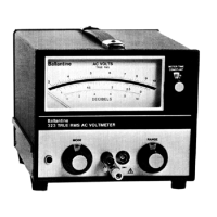
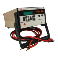
This document describes the Ballantine 323 Series True RMS Voltmeter, an instruction manual published in January 1984. The 323 Series voltmeters are wideband, solid-state, general-purpose instruments designed for precise AC RMS voltage measurements.
Function Description:
The 323 Series True RMS Voltmeter measures the true RMS value of AC signals, including complex waveforms, by performing a mathematical computation: Emrms = √(e1² + e2² + e3² + .... en²). The input signal is first attenuated in three steps (X1, X100, X10,000) by the input attenuator, with a diode clamp protecting the input amplifier from excessive voltage. A three-stage feedback amplifier with a nominal gain of 6 and a bandwidth of approximately 50 MHz then processes the signal. The RMS detector, featuring specially chosen square-law diodes, produces a filtered DC voltage proportional to the square of the input voltage. This DC voltage drives both the analog indicating meter and the DC OUTPUT. The analog meter movement uses a shaped magnet to present a square-root transfer characteristic, allowing the voltmeter to control input signal amplitude, square the input signal, sum harmonic components, and then take the square root to achieve true RMS response. The instrument also offers a "METER + 10 dB" mode, which increases sensitivity by 330 µV on the 1 mV range.
Important Technical Specifications:
- Voltage Range: 12 ranges from 1 mV to 300 V full scale. Minimum measurable voltage is 100 microvolts rms. Maximum measurable voltage is 330 volts rms.
- Range Multiplier: Meter reading + 10 dB applicable on every range and increases sensitivity to 330 µV full scale on the 1 mV range.
- Decibel Range: -80 dBm to + 50 dBm. 0 dBm = 1 mW into 1000 ohms (dBV). -78 dBm to + 52 dBm. 0 dBm = 1 mW into 600 ohms.
- Frequency Range: 2 Hz to 25 MHz. Usable less than 1 Hz to greater than 75 MHz.
- Accuracy (12 Basic Ranges):
- At reference conditions: ± 1% of Full Scale or ± 2% of Reading (whichever is greater) from 2 Hz to 50 kHz.
- Above 100 volts, the state uncertainty doubles.
- Meter + 10 dB Range Multiplier: ± 10% (5 Hz), ± 5% (10 Hz), ± 3% (20 Hz), ± 2% (2 MHz), ± 5% (10 MHz).
- Calibration: True RMS Responding calibrated in volts rms.
- Crest Factor: 10 at 0.7 of full scale deflection, 7 at full scale increasing to 21 at 1/3 full scale deflection. Limited by maximum input rating of 330 V rms of a sinewave or ± 465 volts peak.
- Noise: < 30 microvolts with input terminated in 50 ohms. Noise adds to signal nominally as: Reading = √(Input Signal)² + (Noise)².
- Input Impedance:
- Signal HI to Signal LO: Ranges 100 mV and above: 2 megohms in parallel with 15 pF. 1 mV, 3 mV, and 30 mV ranges: 2 megohms in parallel with 25 pF.
- Signal LO to Case Ground: >40 megohms in parallel with 400 pF.
- Input Terminals: BNC grounded or floating with respect to case. Convertible to floating or grounded operation with binding posts spaced 0.75 inch with supplied Model 618 adapter. Binding post for case ground. A removable grounding link is provided between the case and signal LO binding posts to provide grounded or floating operation.
- Input Over Voltage Protection: 500 volts (dc + peak ac) to 1 kHz continuously applied on all ranges. Limited to 10⁸volt Hz on the 100 mV and all higher ranges and limited to 10⁷volt Hz on the 1 mV, 3 mV, and 30 mV ranges.
- DC Blocking Voltage: ± 500 volts dc peak.
- Floating Operation: Maximum case to signal LO voltage is ± 500 V (dc + peak ac). CMRR: >120 dB at dc. > 80 dB at 60 Hz when ac common mode signal is limited to ten times full scale.
- Meter Response Time: Three meter damping "METER TIME CONSTANTS" are provided by a front panel switch. Proper selection will eliminate meter wobble and filter DC OUTPUT at >2 Hz, >15 Hz, and >100 Hz. 10 dB overload recovery at least damping is less than 2 seconds to full scale and response is less than 1 second to full scale.
- Meter Scales:
- Voltage Scales: Two scales incorporating logarithmic distribution with suppressed zero: .095 to .33, .3 to 1.06.
- dB Scale: Linear scale distribution. Meter scales with 0 dBm = 1 mW into 600 ohms have scale of -8.2 to +2.6 dBm. Meter scales with 0 dBm = 1 mW into 1000 ohms have scale of 0 to 10 dB.
- Reference Conditions: 24°C ± 2°C with < 80% RH. Nominal ac mains voltage ± 2%. Warm-up of 1 hour.
- Accuracy Stability: Warm-Up: Usable after 15 seconds, < 0.5% drift after 15 minutes.
- AC Power Mains Voltage: < 0.2% for a ± 10% change in mains voltage.
- Temperature: 20°C to 28°C: Accuracy as specified. 10°C to 20°C and 28°C to 40°C: Accuracy limits increase by 1.5 times. 0°C to 10°C and 40°C to 55°C: Accuracy limits increase by 3 times.
- Environmental Characteristics:
- Operating: 0°C to 55°C (323-06), -54°C to +75°C (323-07).
- Storage: -40°C to +75°C (323-06), -54°C to +75°C (323-07).
- Humidity: 0 to 95% RH to 40°C Non-Condensing.
- Altitude: Operating: to 3 km. Non-Operating: to 15 km.
- The 323-20MOD40 complies with MIL-T-28800C; Class 5, for shock, vibration, temperature (-40°C limit with batteries), humidity, bench drop, and EMI for radiated interference, conducted susceptibility and conducted interference.
- Power (All Units): 103 to 132 V and 206 to 264 V ac rms (sinusoidal). 50 to 420 Hz. 10 watts maximum.
- Power (323-06 and 323-20-MOD40): Internal Rechargeable Batteries. Operating Time: 40 hours. Recharge Time From Internal Charger: 14 hours. Battery Check using >6 volt limit indication on the meter voltage scale.
- Dimensions: Height: 155 mm (6.1 inches). Width: 198 mm (7.8 inches). Depth: 259 mm (10.2 inches).
- Weight: 3.4 kg (7.5 lbs.). 4.3 kg (9.5 lbs.) with battery.
- Shipping Weight: 5.4 kg (12 lbs.). 6.3 kg (14 lbs.) with battery.
Usage Features:
- Front Panel Controls: Includes METER TIME CONSTANT switch (S2) for DC OUT and meter damping, RANGE selector switch (S1) for full scale reading and dB indication, BNC Input HI Connector (J1), Case Ground Connector (J3), Signal LO Connector (J2), MODE Switch (S3) for mains power on/OFF, METER, METER +10 dB operation, BATT CHG, and test modes.
- Rear Panel Controls: Includes Pilot Light (I1) for AC mains power operation, Meter (M1) for input signal in volts and dB, 115/230 AC Mains Voltage Selector Switch (S4) for mains voltage selection, AC Main Power Cord, AC Mains Fuse (F1), DC OUTPUT Connector (Red) (J4) for HI output signal, and DC OUTPUT Connector (Black) (J5) for LO output signal.
- Floating Operation: The signal LO input can be floated up to ±500 V above case ground.
- DC Output: A DC voltage proportional to the square of the AC input voltage is available at the rear panel banana jacks.
- External Meter/Recorder Drive: The DC output can drive a digital multimeter or strip chart recorder.
- High Voltage AC Divider Probe (Model 1301A): Optionally available to extend the voltage range to 10 kV rms.
- Rear Input Option 04: Provides a BNC connector for rear panel access to the input connector, allowing for 50 ohm terminated systems and high voltage measurements.
Maintenance Features:
- Warranty: One year for materials and workmanship, excluding batteries, electron tubes, vacuum thermocouples, and other listed components.
- Certification: Meets Ballantine specifications and is traceable to the United States National Bureau of Standards.
- Preventive Maintenance: Routine laboratory service recommended every 6 months or 1000 hours of use. Field service recommended every 90 days or 350 hours of use. Full NBS traceable calibration recommended once a year.
- Cleaning: Clean the instrument (inside and outside) with alcohol and a mild detergent solution.
- Repair and Replacement: Use a low-heat capacity grounded soldering iron. Use heat sinks when soldering diodes and semiconductors. Replace components with exact equivalents.
- Rotary Switch Maintenance: Operate switches several times to wipe contacts. Periodically lubricate contacts with spray lubricant.
- Battery Replacement: For units with internal rechargeable batteries, follow specific procedures for disconnection, removal, installation, and initial charging cycles.
- Troubleshooting: A fault-finding guide is provided with symptoms and possible causes/remedies.
- Internal Adjustments: Detailed procedures for DC OUTPUT, Meter Sensitivity, Meter Mechanical Linearity, Output Attenuator Balance, and High Frequency adjustments are provided.
- Backdating Information: Includes schematics and parts lists for previous configurations of the 323 Series Voltmeters, as well as instructions for chopper replacement on older models.