2 english
BTL B/ZNC_ 00- _ _ _ _ -C15A _ _ _0-000S35
Magnetostrictive Linear Position Sensor – Rod Style
Installation (continued)
If installed in a hydraulic cylinder, the magnet should not
make contact with the rod. Minimum bore diameter in the
support piston:
Rod diameter Bore diameter D2
10.2mm At least 13mm
NOTICE
Interference in function
Improper installation can compromise the function of the
BTL and result in increased wear.
► Ensure that the contact surface of the BTL is in full
contact with the mounting surface.
► Seal the hole perfectly (O-ring/flat seal).
Mounting in a hole with internal thread (mounting
hole)
1. Make a mounting hole with thread (possibly with
countersink for the O-ring).
2. Screw the BTL with mounting thread into the mounting
hole (max. torque75Nm).
Mounting in a through-hole
Depending on the version, the BTL comes with a M18×1.5
thread (according to ISO) or 3/4"-16UNF (according to
SAE).
1. Guide the BTL through the hole.
2. Screw the mounting nut (max. torque75Nm) onto the
mounting thread on the rod side.
Further steps
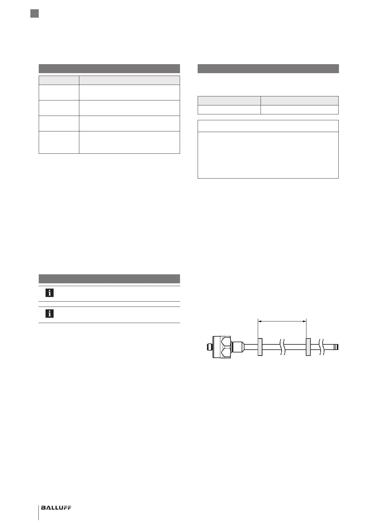
► Install the magnet (accessory).
When using multiple magnets a minimum separation of
65 mm must be maintained between them.
≥ 65
► From measuring length of 500mm: Support the rod
and if necessary screw on at the end.
Display elements
Signal Meaning
Green Normal function
Magnet is within the measuring range.
Yellow flas-
hing, 3Hz
Warning
Magnet is outside the measuring range.
Red flashing,
1Hz
Measurement error
No magnet
Red flashing,
3Hz
Output error
1)
Short-circuit at voltage output or
interruption on current output.
1)
Is only displayed for versions with 2 current outputs if the error is
present at the same time at both outputs.
With 1magnet and 2 outputs the priority of the LED
display is as follows (highest to lowest priority):
– Output error
– Measurement error
– Warning
– Normal function
For FMM (Flexible Magnet Mode) with 1magnet the LED
display relates to output 1 (output 2 issues the error value
continuously).
For FMM (Flexible Magnet Mode) with 2magnets the LED
display shows the status with the highest priority of both
outputs.
More than 2 magnets are ignored.
Installation
For examples and further information on
installation, see the user’s guide.
Suitable nuts for the mounting thread are
available as accessories.
We recommend using non-magnetizable material to mount
the BTL and magnet.
If using magnetizable material, the BTL must be protected
against magnetic interference through suitable measures
(e.g. spacer ring made of non-magnetizable material, a
suitable distance from strong external magnetic fields).
 Loading...


