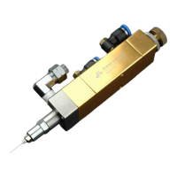
The BV-520P is a normally closed, fail-safe, adjustable opening needle valve designed for precise fluid dispensing. Its operation is based on air pressure acting on a piston to retract a needle from its seat, allowing fluid to flow. The amount of fluid dispensed is influenced by the length of time the valve is open, fluid reservoir pressure, needle stroke, and fluid viscosity.
Technical Specifications:
- Size: 114.6mm x 26.9mm (4.510” x 1.060” diameter)
- Weight: 300g
- Fluid Inlet Thread: 1/8 PT Female
- Fluid Outlet: M3.5 x 0.6P TAP
- Air Pressure Required: 4.8 bar (70 psi)
- Maximum Input Fluid Pressure: 21 bar (300 psi)
- Mounting:
- 1/4-20 Thread UNC DP5 (Air Cylinder Body)
- M6 x 1P DP5 TAP (Fluid Chamber)
- Operation Frequency: Exceeds 400 per minute
- Output Variation: +- 1% nominal
Construction Materials:
- Air Cylinder Body: SUS 303
- Fluid Chamber: SUS 303
- Piston: SUS 303
- Needle: SUS 303
- Tip Adapter/Needle Seat: SUS 303
- Needle Packing: Teflon
Usage Features:
The BV-520P can be operated in any position without affecting flow, and vibration typically has no effect on performance. It can also be moved in and out of dispense position at high-cycle rates, such as when installed on a reciprocation device on a production line, without impacting dispensing performance.
Stroke Control Reference:
The valve features a stroke control reference to calibrate the stroke control setting or document the dispensing process. To calibrate, the stroke control knob is fully closed. The set screw is then loosened, and the stroke reference ring is turned until the zero on the ring aligns with one of the two reference marks on the valve body. Tightening the set screw completes the calibration.
Setup Procedure:
- Mounting: Secure the BV-520 valve using an appropriate fixture. This can be done via the 1/4-20 Thread UNC DP5 on the air cylinder body or the M6 x 1P DP5 TAP on the fluid chamber.
- Air Line Connection: Connect the control air line to the valve controller or pneumatic switch responsible for operating air control.
- Fluid Feed Connection: Attach the fluid feed hose to the fluid inlet fitting and the fluid reservoir.
- Fluid Chamber Repositioning: The fluid chamber with its inlet fitting can be rotated to avoid interference with machine parts. To do this, turn the needle stroke control out two full turns, then rotate the chamber to the desired position. Note: Do not rotate the fluid chamber more than one complete turn.
- Fluid Reservoir: Fill the fluid reservoir and ensure the cover is secured and all connections are tight.
- Reservoir Pressure Setting: For low viscosity fluids, start with approximately 0.3 bar (5 psi). For higher viscosity fluids, use 1.4 to 2.8 bar (20 to 40 psi). Adjust as necessary. Note: For very small amounts of solvents or watery fluids, a 0 to 1.0 bar (0 to 15 psi) precision regulator is recommended for reservoir pressure control.
- Needle Stroke Setting: Begin with the needle stroke at one full turn open.
- Valve Control Air Pressure: Set the valve control air pressure to 4.8 bar (70 psi).
- Initial Flow Test: Open the valve with an air pulse long enough to fill the valve and initiate fluid flow. Test the dispensed amount with a nominal time setting.
- Adjustment: Increase or decrease reservoir pressure, needle stroke, and valve open time to achieve the desired deposit size.
Maintenance and Cleaning:
Normal Cleaning:
Normal cleaning involves purging the valve with an appropriate solvent. The needle seat can be removed (after bleeding off reservoir pressure) for cleaning without dismounting the valve.
- Caution: Always relieve reservoir pressure and disconnect power before performing any maintenance. Do not use sharp instruments to scrape or clean components, as scratches can cause leaks.
Thorough Cleaning and Needle Packing Replacement:
- Remove Needle Stroke Control: Turn counterclockwise until free to prevent damage to the needle and seat during reassembly.
- Remove Inlet Fitting: Remove the inlet fitting and seat assembly from the fluid chamber.
- Remove Fluid Chamber: Turn the fluid chamber counterclockwise until free from the cylinder body. Then remove the O-ring from the fluid chamber.
- Remove Needle Packings: Insert a packing extraction tool (not included) through the outlet end of the fluid chamber and gently push out the packings.
- Remove Remaining Packings: Remove any remaining packings and the packing spring from the needle. Note: The lower cylinder needle O-ring is held by a flat retaining washer that also serves as the packing spring seat. Ensure it is back in place before reinstalling the packing spring.
- Clean Needle: Clean the needle with a cloth dampened in solvent.
- Lubricate and Reinstall: Lubricate the needle, then reinstall the needle packing spring and a new packing kit.
- Install New O-ring: Install a new O-ring on the fluid chamber. Screw the cylinder onto the fluid chamber, hand tighten only. The chamber can be turned back out up to one turn to orient the fluid inlet fitting.
- Reinstall Tip Adapter/Seat Assembly: Reinstall the tip adapter/seat assembly.
- Reinstall Piston Return Spring: Place one thrust washer over the spring pilot (at the top of the piston), then the other thrust washer into the needle stroke control, followed by the spring.
- Reinstall Needle Stroke Control: Align the piston return spring with the spring pilot. Turn the needle stroke control clockwise until it stops, then back it out to the desired setting.
Piston and Needle Assembly or Piston O-ring Replacement:
- Remove Needle Stroke Control: Turn counterclockwise until free.
- Remove Piston Return Spring: Remove the piston return spring and thrust washers from each end of the spring.
- Remove Snap Ring: Use snap ring pliers to remove the snap ring.
- Pull Assembly: Pull the piston and needle assembly out of the cylinder using small pliers on the spring pilot (at the top of the piston). Note: The piston and needle assembly is replaced as a unit and cannot be disassembled.
- Clean Cylinder Body: Clean the cylinder body wall and apply lubricant.
- Replace O-ring: Replace the O-ring on the piston, apply lubricant, then reinstall it in the cylinder.
- Reinstall Snap Ring: Reinstall the snap ring.
- Reinstall Piston Return Spring: Place one thrust washer over the spring pilot, then the other thrust washer into the needle stroke control, followed by the spring.
- Reinstall Needle Stroke Control: Align the piston return spring with the spring pilot. Turn the needle stroke control clockwise until it stops, then back it out to the desired setting. Note: Do not overtighten the needle stroke control, as this may cause needle damage.
Leak Test:
After maintenance, the valve should be leak tested before returning to service.
- Set Needle Stroke: Set the needle stroke control knob to two turns open.
- Shut Off Actuating Air: Install an air hose in the valve's fluid inlet and connect it to a 7 bar (100 psi) air supply.
- Submerge: Submerge the needle seat and nozzle in water. If air bubbles appear, perform the reseating procedure.
Reseat Needle Seat and Nozzle Assembly:
- Disconnect Air: Disconnect or shut off all air to the valve.
- Open Needle Stroke Control: Open the needle stroke control two turns.
- Loosen and Retighten Needle Seat: Using an appropriate wrench, loosen the needle seat one full turn, then turn it back in and retighten. This helps small irregularities on the needle and seat conform.
- Restore Air and Cycle: Restore actuating air and cycle the valve a few times, then perform the leak test again.
- Repeat: Steps 3 and 4 may be repeated up to three times for satisfactory results.
- Replace Parts: If the valve continues to leak after three attempts, replace the needle, needle seat, and nozzle.
Troubleshooting Guide:
- No Fluid Flow:
- Air operating pressure too low: Increase to 4.8 bar (70 psi).
- Reservoir air pressure not high enough: Increase pressure.
- Needle stroke adjustment closed: Open counterclockwise one full turn.
- Clogged valve head or output needle seat/nozzle: Clean the valve.
- Steady Drip:
- Worn needle and seat, or particle holding needle off seat: Remove needle seat and nozzle, clean, inspect for wear. Replace worn or damaged parts.
- Fluid Leaks Out Drain Hole:
- Worn needle packings: Replace needle packings.
- Inconsistent Deposits:
- Fluctuating air pressure controlling the valve.
- Fluctuating air pressure supplying the reservoir.
- Air pressure controlling the valve less than 4.8 bar (70 psi).
- Valve open time not constant.
- Valve controller not providing a consistent output.
- Correction: Ensure air pressures are constant, valve operating air pressure is 4.8 bar (70 psi), valve open time is constant, and valve controller provides consistent output.