Installing the VLINX ESP Software
Manual Documentation Number: ESP904-0504 Chapter 2 11
B&B Electronics Mfg Co Inc – 707 Dayton Rd - PO Box 1040 - Ottawa IL 61350 - Ph 815-433-5100 - Fax 815-433-5104 – www.bb-elec.com
B&B Electronics Ltd – Westlink Commercial Park – Oranmore, Galway, Ireland – Ph +353 91-792444 – Fax +353 91-792445 – www.bb-europe.com
C
C
h
h
a
a
p
p
t
t
e
e
r
r
2
2
:
:
M
M
A
A
K
K
I
I
N
N
G
G
T
T
H
H
E
E
H
H
A
A
R
R
D
D
W
W
A
A
R
R
E
E
C
C
O
O
N
N
N
N
E
E
C
C
T
T
I
I
O
O
N
N
S
S
Package Checklist
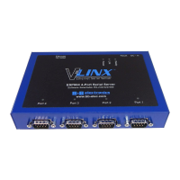
The ESP904 4-port serial server is shipped with the following items
included:
9 ESP904 Serial Server Module
9 Power supply
9 This manual
9 CD-ROM disc with manual, VLINX ESP Manager and Virtual COM
Driver software for Windows 98/ME/2000/XP/NT 4.0
Figure 7. Side View of the ESP904 – when vertically mounted
Installing the VLINX ESP Software
12 Chapter 2 Manual Documentation Number: ESP904-0504
B&B Electronics Mfg Co Inc – 707 Dayton Rd - PO Box 1040 - Ottawa IL 61350 - Ph 815-433-5100 - Fax 815-433-5104 – www.bb-elec.com
B&B Electronics Ltd – Westlink Commercial Park – Oranmore, Galway, Ireland – Ph +353 91-792444 – Fax +353 91-792445 – www.bb-europe.com
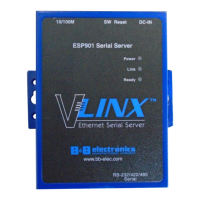
ESP904 Connections, Indicators and Reset Switch
The ESP904 has:
• Seven indicator LEDs
• One Ethernet connector
• A power connector
• A recessed reset switch
• Four serial port connectors
Indicator Lights
Light Indication
Power
Red - power is applied
Link
Yellow – 10BaseT Ethernet connection established
Green – 100BaseTX Ethernet connection established
Ready
Flashing Green – system is ready
Serial (4) When set up as a TCP server:
Steady Green - client has made a connection,
communications starting
Flashing Green – data present at serial port
Light off – connection closed
When setup in UDP mode:
Steady Green (all ports)
Flashing Green – data is being transmitted
Ethernet Connector
The ESP904 has a standard RJ-45 receptacle mounted in the top edge of the
chassis. The ESP904 can be connected to an Ethernet hub, switch, or wall
plate using a standard straight-through RJ-45 (male) Ethernet cable. To
connect directly to an RJ45 Ethernet port on a PC or laptop a crossover
Ethernet cable must be used.
N
N
o
o
t
t
e
e
:
:
Refer to Appendix D for details on Network Cables