Do you have a question about the B&B Electronics Vlinx VESP211 and is the answer not in the manual?
Explains what VESP211 Serial Servers are and their core function of connecting serial devices to Ethernet networks.
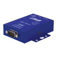
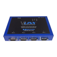
Details the different models within the VESP211 family and their specific serial interface connectors.
Lists the key features and capabilities of the VESP211 serial server product.
Introduces the Vlinx Manager software for configuring serial servers, its GUI, and ease of use.
Lists the items included when purchasing VESP211 Serial Servers.
Describes the rugged, panel-mountable enclosure and mounting options for VESP211 models.
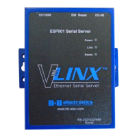
Explains the function and meaning of the Ready, Ethernet, and Serial LED indicators on the VESP211.
Details the location and functionality of the recessed reset switch for various operations.
Describes the RJ45 receptacle for Ethernet connections and the type of cable used.
Outlines the different serial port connector types (DB-9M, terminal blocks) used by VESP211 models.
Specifies the barrel jack connector for power, its voltage, and maximum wattage requirements.
Explains how VESP211 modules can be panel mounted and mentions an optional DIN rail adapter.
Instructs on how to connect the DC power supply to the serial server.
Guides on connecting the serial server to RS-232, RS-422, and RS-485 serial devices.
Explains how to connect the serial server to an Ethernet network using an RJ45 connector.
Outlines the methods for configuring the serial server via network or serial port.
Describes the different operational modes: Direct IP, Virtual COM Port, and Paired Mode.
Introduces the Vlinx Manager configuration window layout and its main areas.
Explains the function of various icons within the Vlinx Manager configuration window.
Details the information displayed in the table for discovered serial servers.
Describes the web browser-like configuration pane and its components.
Guides the user on how to log in to a serial server using Vlinx Manager.
Explains how to move between configuration pages and the importance of saving settings.
Details how to change the serial server's name and set a login password.
Covers configuring dynamic (DHCP) or static IP addressing for the serial server.
Explains how to configure serial port parameters like mode, baud rate, data bits, parity, and flow control.
Covers configuring port protocols like UDP, TCP, VCOM, and Paired modes.
Details how to configure the serial server to operate as a TCP client or server.
Explains how to configure the serial server for UDP communication, including send and receive options.
Describes how to set up VCOM operation for remote COM port functionality.
Explains how to set up Paired Mode for serial tunneling between two devices.
Covers configuring connection behavior and data packet transmission.
Details how to use network and serial watchdogs to force connections closed.
Explains settings for character count, forced transmit, and delimiters for data packet sending.
Guides on saving current configurations and restoring default settings.
Instructs on how to add virtual COM ports using the Vlinx Manager software.
Details the process of removing virtual COM ports via Vlinx Manager.
Explains how to download firmware files from an FTP site or a local file.
Provides steps for uploading new firmware to the serial server using Vlinx Manager.
Guides on how to test the network connectivity of a serial server.
Explains how to test the functionality of a virtual COM port connection.
Defines baud rate as communication speed and its configuration requirements.
Explains character count for buffering data before network transmission.
Describes the use of configuration files for saving and applying settings.
Details the serial port parameters for data bits, parity, and stop bits.
Explains how delimiters control character reception and network transmission.
Defines DHCP and its role in assigning IP addresses to the serial server.
Indicates the firmware version and the ability to update it.
Describes flow control settings for handshaking and message control.
Explains forced transmit for buffering data based on time.
Defines inter-character timeout for buffering data between received characters.
Explains the importance of IP address for network access and DHCP/static configuration.
Describes configuring PC network settings to match the serial server.
Details configuring the serial server via console mode to match PC network settings.
Defines the MAC address as a unique hardware identifier.
Lists available network protocols: TCP, UDP, VCOM, and Paired Mode.
Explains network watchdog for detecting idle connections and forcing closure.
Describes Paired Mode for serial tunneling and its client/server configuration.
Advises on setting and changing the serial server's login password.
Lists the four serial interface modes: RS-232, RS-422, RS-485 2-wire, RS-485 4-wire.
Defines the serial server name as a unique, valid hostname.
Explains serial watchdog for detecting serial inactivity and forcing connections closed.
Specifies the network mask used by the serial server on a subnetted network.
Defines TCP as a reliable, connection-oriented network communication protocol.
Defines UDP as a connectionless protocol for broadcasting and receiving data.
Lists the default configuration settings for the VESP211 serial server.
Provides detailed technical specifications for the VESP211 serial server.
Shows the physical dimensions of the VESP211 serial server in inches and millimeters.
Details the pin assignments for DB-9M connectors and terminal blocks.
| Serial Interface | RS-232/422/485 |
|---|---|
| Ethernet Ports | 1 |
| Power Input | 9-30 VDC |
| Model | VESP211 |
| Category | Server |
| Connector | DB9 |
| Operating Temperature | -40°C to 85°C |