Section 3 - Initial Setup and Connections Vlinx VESR4x4 Serial Server
Page 16 of 67 www.bb-elec.com/
www.bb-europe.com/
RS-485
The RS-485 interface supports 2-wire or 4-wire operation.
When configured for 4-wire operation the connection supports two signal
pairs: TDA (-), TDB (+), RDA (-), RDB (+) and GND. This makes full-duplex
operation possible. The data lines are differential pairs (A & B) in which the B
line is positive relative to the A line in the idle (mark) state. Ground provides a
common mode reference.
When configured for 2-wire operation the connection supports one signal
pair: Data A (-) and Data B (+) signal channels using half-duplex operation.
The data lines are differential with the Data B line positive relative to Data A in
the idle (mark) state. Ground provides a common mode reference.
Note: Refer to Appendix D for connector pinout information.
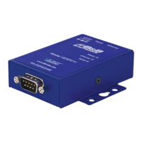
Figure 10. VESP211 Connections
Connecting VESP211 Serial Servers to a Network
Ethernet Connection (10BaseT/100BaseTX)
The Ethernet connection uses a standard RJ45 connector. A standard
network cable is connected from the serial server to a network drop. PCs
configuring and/or communicating with the serial server are also connected to
the network.
 Loading...