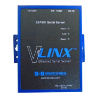
Section 9 - Appendix Vlinx VESP211 Serial Server
Page 61 of 67 www.bb-elec.com/
www.bb-europe.com/
Controls, Indicators and Connector Specifications
Hold in for 0 to 2 seconds for hardware reset
Hold in for 2 to 10 seconds for Console Mode (Do a hardware reset
or recycle power to exit Console Mode)
Hold in for more than 10 seconds to reset to factory defaults
Color = Green
On = Port open
Blink = Data traffic
Color = Yellow or Green
On = 100BaseTX
Off = 10BaseT
Blink = Data traffic
Color = Green
Blink (once per second) = System OK
Off = System NOT OK
10BaseT/100BaseTX Ethernet
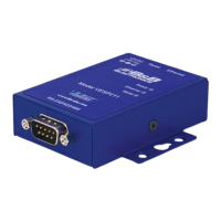
VESP211: DB9 connector
VESP211-232: DB9 connector
VESP211-485: terminal block connector
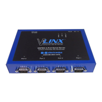
Serial Interface Specifications
RS-232/422/485 software selectable
TXD, RXD, RTS, CTS, DTR, DSR, DCD, GND
TXDA(-), TXDB(+), RXDA(-), RXDB(+), GND
TXDA(-), TXDB(+), RXDA(-), RXDB(+), GND
75, 150, 300, 600, 1200, 2400, 4800, 7200, 9600, 14400, 19200,
28800, 38400, 57600, 115200, 230400
None, even, odd, mark, space
Auto 1K ohm pullups and pulldowns
120 ohm with user-installed jumpers
 Loading...