NETWORK COMPASS USER MANUAL
CONTENTS
GENERAL INTRODUCTION TO B&G NETWORK.........................................................2
INTRODUCTION TO NETWORK COMPASS.................................................................3
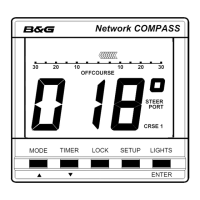
COMPASS DISPLAY UNIT.............................................................................................4
EXAMPLE SYSTEMS USING NETWORK COMPASS...................................................4
INITIAL POWER-UP........................................................................................................5
SETTING THE DISPLAY BACK LIGHTING ...................................................................6
THE OFF COURSE DISPLAY.........................................................................................7
SETTING THE COURSE MEMORIES ............................................................................8
THE XTE DISPLAY .........................................................................................................9
THE RUDDER DISPLAY...............................................................................................10
THE HEAD/LIFT DISPLAY ...........................................................................................11
USING THE TIMER.......................................................................................................12
SETTING THE TIMER...................................................................................................13
ENABLING/DISABLING THE TIMER BEEPS..............................................................13
ENABLING THE OFF COURSE ALARM......................................................................14
SETTING THE COMPASS DAMPING ..........................................................................14
SETTING THE COMPASS OFFSET.............................................................................15
SETTING THE VARIATION ..........................................................................................15
SETTING THE DISPLAY FOR TRUE OR MAGNETIC READINGS .............................16
ENABLING THE HEAD/LIFT MODE.............................................................................16
SELECTING THE DISPLAY MODE..............................................................................17
CALIBRATING THE COMPASS...................................................................................17
OPERATION WITH AUTOPILOTS ...............................................................................18
TROUBLESHOOTING ..................................................................................................19
INSTALLATION ............................................................................................................20
SITING THE FLUXGATE ..............................................................................................21
INSTALLATION DATA..................................................................................................22
SPECIFICATIONS.........................................................................................................23
1