Do you have a question about the B&R Automation Panel 5000 and is the answer not in the manual?
The provided document is the "Automation Panel 5000 User's manual V2.11" from B&R Industrial Automation GmbH, dated July 2020. It details the modular Automation Panel 5000 product generation, which can function as a remote panel or part of a Panel PC.
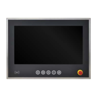
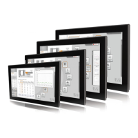
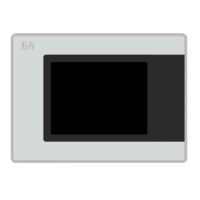
The Automation Panel 5000 series serves as the foundation for both the Automation Panel 5000 and two Panel PC variants: Panel PC 2100 or Panel PC 2200 swing arm devices. These panels integrate a display and a touch screen, offering various display sizes, touch screen technologies, and mounting systems. They can also be equipped with operating elements.
To operate as a complete system, the panels must be combined with a link module (for Automation Panel 5000) or a system unit (PPC2100 or PPC2200 with Automation Panel 5000). Single-touch panels are identified by model numbers starting with 5AP5120.xxxx-xxx, while multi-touch panels begin with 5AP5130.xxxx-xxx. Multi-touch panels with an expansion option use model numbers starting with 5AP5230.xxxx-xxx.
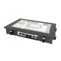
Link modules are crucial components that provide various graphics interfaces and connections. An Automation Panel is assembled by installing a link module onto a panel. These modules cannot be operated independently.
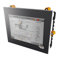
Mounting units are installed on the back of the panel to protect the installed link module or system unit. They offer varying degrees of protection: IP65, IP54, IP20, or IP10, depending on the variant. Flanges, such as 5ACCFL00.0000-000, are installed on swing arm mounting units to connect the Automation Panel or Panel PC to a swing arm system. VESA brackets, used with VESA mounting units like 5ACCMA01.0100-000, allow for VESA 100 or VESA 75 installation.
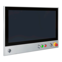
Expansion units can be added to AP5230 panels with an expansion option. These units can be expansion covers, which have cutouts for user-installed operating elements, or expansion units with pre-integrated operating elements. Handles can also be installed on the sides of the panel for ergonomic operation.
The Automation Panel 5000 supports various connection options to a B&R industrial PC, including SDL, DVI, SDL3, or SDL4 operations.
Panels: The panels come in various sizes and resolutions:
Power consumption varies by panel size and resolution, ranging from 11 W for a 15" single-touch panel to 29.5 W for a 24.0" multi-touch panel.
Link Modules:
Mounting Units:
5ACCMA00.0000-000 (without USB interface), 5ACCMA00.0001-000 (1x rear USB interface), 5ACCMA00.0002-000 (2x rear USB interface) for swing arm mounting, all offering IP65 protection.5ACCMA01.0100-000 (VESA mounting unit) offers IP20 protection.5ACCMA00.0100-000 (HMI mounting unit VESA IP54) and 5ACCMA00.0101-000 (HMI mounting unit VESA IP54 w/USB) provide IP54 protection when used with suitable cable grommets.Flanges:
5ACCFL00.0000-000 (Rotary flange): Range of rotation ±150°, for 48 mm shaft diameter swing arm systems. Weight: 530 g.5ACCFL00.0100-000 (Swivel-tilt flange): Range of rotation ±150°, tilting range ±15°, for 48 mm shaft diameter swing arm systems. Weight: 1666 g.5ACCFL00.0200-000 (Rittal flange adapter): For Rittal coupling CP40 (steel). Weight: 93 g.Expansion Units (for AP5230 panels):
5ACCKP00.xxxx-000) offer 7 to 14 cutouts for user-installed operating elements.5ACCKP01.xxxx-000, 5ACCKP03.xxxx-000, 5ACCKP04.xxxx-000, 5ACCKP05.xxxx-000) include a front USB interface, pushbuttons (green, red, blue), selector switch, key switch, emergency stop device, and/or RFID read/write unit.Environmental Properties:
5ACCMA00.000x-000 mounting unit and correct installation). IP54 on all sides (with 5ACCMA00.010x-000 mounting unit and correct installation).Easy Customization: The modular design allows the Automation Panel 5000 to be easily customized. It can be configured with different panels, link modules, mounting units, flanges, and expansion units to meet specific application needs.
Connection Options:
Touch Screen Calibration: B&R touch screen devices are pre-calibrated at the factory. Recalibration is generally not required for replacement parts of the same model/type but is recommended for best results and user adaptation. Drivers are available for various Windows IoT Enterprise, Windows Embedded, Windows XP Professional, and B&R Linux operating systems.
Display Brightness Control: Brightness can be adjusted via the B&R Control Center in SDL, SDL3, or SDL4 modes, or using dedicated brightness buttons on the SDL/DVI receiver in DVI mode.
Button/Switch and LED Configuration: Each button and LED can be individually configured using B&R tools like Key Editor, KCF Editor, or Control Center for Windows, or Visual Components for Automation Runtime. They are processed by a matrix controller in a 128-bit string.
Cleaning: The device should only be cleaned when switched off. A cloth moistened with dishwashing detergent, screen cleaner, or alcohol (ethanol) can be used. Abrasive cleaners, aggressive solvents, chemicals, compressed air, or steam cleaners are not permitted. Touch screens should be cleaned regularly.
Increasing Display Service Life:
Pixel Errors: Faulty pixels are considered a manufacturing process characteristic and are not grounds for complaint or warranty claim.
Repairs/Complaints and Replacement Parts: Unauthorized opening or repair is not permitted and can result in injury or damage. Repairs must be carried out by authorized qualified personnel at the manufacturer's premises. Repair orders or complaints are processed via the B&R Material Return Portal. Only B&R-approved components are allowed for maintenance.
Firmware Upgrade: BIOS and firmware on B&R devices should be kept up to date. Firmware upgrades for Automation Panels, SDL3 Converters, and SDL4 Converters are available from the B&R website. The device must not be switched off or reset during an upgrade.
Temperature Monitoring: A sensor in the display monitors the panel temperature. Maximum specified temperatures are provided, and if exceeded, no alarm is triggered. Temperatures can be read out via BIOS, B&R Control Center, B&R ADI Development Kit, B&R ADI .NET SDK, B&R HMI Service Center, B&R HMI Diagnose, B&R PVI ADI line, B&R ADI SNMP Agent, or Automation Runtime library.
| Brand | B&R |
|---|---|
| Model | Automation Panel 5000 |
| Category | Touch Panel |
| Language | English |