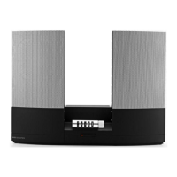
Do you have a question about the Bang & Olufsen BEOCENTER 2000 and is the answer not in the manual?
Defines conditions for measuring DC and AC voltages, signal paths, and switch positions.
Explains wire connections gathered into bundles and codes used to indicate their destinations.
Describes the use of co-ordinate systems on PC boards for component placement.
Details the AM RF, Volume/Tone Control, and FM Preset sections of the device.
Covers the Power Amplifier and Power Supply circuits, identified by PC board numbers.
Provides a comprehensive list of electrical components used in the FM Section, PC2.
Lists mechanical parts for the Tape Recorder module, including covers, screws, and springs.
Details general mechanical parts such as covers, screws, rails, and holders.
Lists mechanical components for recording level and autostop mechanisms.
Lists components for the radio section, including tuner, PC boards, and switches.
Provides a list of mechanical parts for the gramophone deck, including adaptors, screws, and springs.
Procedure for adjusting tuning voltage for FM reception using specific resistors.
Steps for aligning the tuner circuit using a sweep generator and oscilloscope.
Alignment for IF stage, detector circuit, and muting sensitivity.
Procedure for adjusting the stereo decoder and 114 kHz filter.
Describes testing and adjusting playback frequency path, bias oscillator, and record current.
Procedures for setting tape speed, playback level, and adjusting head height/azimuth.
Adjusting channel separation and aligning the AM intermediate frequency stages.
Adjusting the MW and LW oscillator and aerial circuits for optimal reception.
Ensuring correct engagement of the idler wheel with take-up spool and capstan.
Checking clearance on the pressure roll assembly for correct pause function.
Directions for lubricating components during overhauls or replacements.
Procedures for setting turntable speed (33/45 RPM) and adjusting turntable height.
Ensuring correct operation of the rewind and fast forward mechanisms.
Details the 8 output voltages of the Beocenter 2000 power supply and their circuit usage.
Presents a block diagram illustrating the FM and AM signal paths and key circuits.
Instructions for adjusting pick-up height, balance, parallelism, and antiskating.
Illustrates the signal path for the left and right channels of the taperecorder playback.
Describes the function and adjustment of the motor switch (15RL1).
Details power output, distortion, frequency range, and other amplifier performance metrics.
Provides technical details for FM and AM reception, including sensitivity and frequency ranges.
Lists specifications for the record player, stylus, tracking force, and speeds.
Details specifications for the tape recorder, including cassette type, tape heads, and speed.
Provides guidance on the disassembly process for the device.
Diagram showing the wiring of the transformer for servicing purposes.
Presents general data like power supply, frequency, consumption, dimensions, and weight.
| Brand | Bang & Olufsen |
|---|---|
| Model | BEOCENTER 2000 |
| Category | Speakers |
| Language | English |
