Do you have a question about the Bang & Olufsen Beolab 4000 MKII 6642 and is the answer not in the manual?
| Frequency response | 50 - 20, 000 Hz |
|---|---|
| Weight | 3.6 kg |
| Amplifier power | 100 W |
| Cabinet principle | Bass reflex |
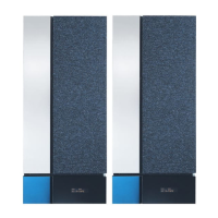
| Type | Active speaker |
| Power output | 100 W |
| Frequency range | 55 - 20, 000 Hz |
| Woofer | 100 mm |
| Dimensions W x H x D | 280 x 420 x 240 mm |
| Woofer Size | 100 mm |
| Inputs | RCA |
| Finish | Aluminum |
Procedures for servicing at customer location.
Methods for diagnosing and locating faults.
Importance of ESD-mat for electronic components.
Step-by-step guide for insulation testing.
Setting potentiometers after Main PCB replacement.
Adjusting audio output levels for bass and treble.
Tips for fixing hum issues in the loudspeaker.
Steps to verify the Switch Mode Power Supply.
Essential ESD precautions for module handling.
How to safely disconnect cables from the unit.
Instructions for removing the front frame.
How to disconnect cables connected to speaker units.
Steps to unscrew the amplifier module.