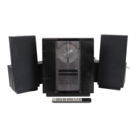
Do you have a question about the Bang & Olufsen BeoSound 3000 2671 and is the answer not in the manual?
| Brand | Bang & Olufsen |
|---|---|
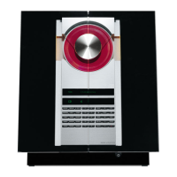
| Model | BeoSound 3000 2671 |
| Category | Stereo System |
| Language | English |
Details power supply and input select circuitry.
Covers the FM/AM/RDS stereo decoder.
Guidelines for service use of specifications.
Technical specifications for the FM tuner section.
Technical specifications for the AM tuner section.
Transformer wiring for specific types.
Transformer wiring for specific types.
Transformer wiring for specific types.
Transformer wiring for specific types.
Transformer wiring for specific types.
General guide to understanding diagrams.
Important cautions regarding laser product and batteries.
Wiring for PCB9 (Light and Motor Control).
Wiring for PCB5 (Display and Keyboard).
Wiring diagram for PCB12.
Block diagram of the frontend tuner section.
Block diagram of the AM tuner section.
Block diagram of the CD PRO mechanism.
PCB drawing for the frontend tuner (PCB86).
PCB drawing for the FM/AM detector (PCB86).
PCB drawing for stereo decoder and power section (PCB86).
PCB drawing for RDS, µP, and IIC bus filter (PCB86).
PCB drawing of the Tuner module.
PCB drawing for the µP and µPH8 interface (PCB2).
PCB drawing for light/motor control and IR (PCB9).
PCB drawing for input select and pre-amplifier (PCB12).
PCB drawing for the Master Link interface (PCB12).
PCB drawing for power supply and transformer (PCB12, PCB15).
PCB drawing for PCB12 components.
PCB drawing for door sensors (PCB20, PCB21).
PCB drawing for the CD interface (PCB89).
PCB drawing for CD servo and decoder (PCB80).
PCB drawing for display and keyboard (PCB5).
Electrical parts list for PCB86 (Tuner).
Overview of test modes and their functions.
Tuner variant setup for different regions.
Service Error detection and deletion.
Step-by-step guide to replace the CD mechanism.
Procedure to remove the gearbox for the CD clamp.
Instructions for mounting the wire for the glass doors.
Steps for adjusting the glass doors.
Test procedure for Master Link data interface.
Explains the theft protection PIN code system.
How to use the service code for extended functionality.
Information on Master code usage and ordering.
Notes on exchanging the microprocessor module.
Procedure for exchanging EEPROM on PCB3.
Exchanging both processor and EEPROM.
How to set and enter the PIN code.
Steps to activate the PIN code system.
Procedure for entering the PIN code.
How to deactivate the PIN code system.
Steps to take if the PIN code is forgotten.
How to change the existing PIN code.
Procedure for performing an insulation test.