EasyManua.ls Logo

Bang & Olufsen Type 2651 User Manual

Bang & Olufsen Type 2651
76 pages
To Next Page IconTo Next Page
Page #1 background imageLoading...
Page #1 background image
rt.
Bang&Olufsen
BeoSound
Century
Typ€ 2651, 2652, 2654, 265/l
SERVICE MANUAL
Circuit Description
3540178 Danish
3540179
English
3540180 German
3540181 Fi€nch
Question and Answer IconNeed help?

Do you have a question about the Bang & Olufsen Type 2651 and is the answer not in the manual?

Bang & Olufsen Type 2651 Specifications

General IconGeneral
TypeStereo System
CategoryStereo System
ManufacturerBang & Olufsen
IM Distortion0.1%
Frequency Range20 Hz - 20 kHz
FM Tuner Range87.5 - 108 MHz
Harmonic Distortion0.1%
Frequency Response+/- 1 dB
Power Consumption150 W

Summary

Service Manual

Circuit Description

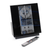
Overview of the internal circuitry and components.

Specification Guidelines

Brief Operation Guide

Diagram A FM/AM Decoder

Diagram B Tape Digital

Diagram C Tape Analog

Diagram E CD Servo

Diagram F CD Decoder

Diagram J Output Amplifier, Left & Crossover Network, Left

Diagram K Output Amplifier, Right & Crossover Network, Right

Tuner Adjustment Table

Varicap Alignment Adjustments

Table detailing adjustments for VHF/AM/LW varicap tuning.

Adjustment Procedure

Tuner Adjustment Steps

Step-by-step guide for tuning adjustments.

Tape Recorder Azimuth Adjustment

Procedure for setting the tape head azimuth.

Tape Adjustments

Speed and Torque Adjustment

Adjusting tape speed and take-up torque using test tapes.

Playback Level and Bias Adjustment

Setting playback level and bias for optimal tape performance.

Tape Record Current and CD Laser Adjustment

Record Current Adjustment

Procedure for adjusting the recording current for tape bias.

CD Laser Current Adjustment

Steps for setting the laser current for CD playback.

Loudspeaker and Speaker Level Adjustments

Speaker Bass/Treble Level Adjustment

Adjusting bass, treble, and volume levels for the speakers.

Speaker Replacement Adjustments

Procedures for adjusting speaker levels after replacement.

PCB Replacement Adjustments

PCB 3 or 3IC4 Replacement

Steps for replacing PCB 3 or 3IC4 and storing values.

Repair Tips

Test Functions Overview

List of diagnostic functions available in TEST MODE.

Test Mode Functions and Specific Tests

Test Mode Overview

Instructions for entering and exiting TEST MODE.

CD Test Procedures

CD Playback and Error Testing

Detailed steps for testing CD functionality and error detection.

Laser Supply Voltage Check

Laser Supply Feedback Check

Method for checking the laser supply feedback system.

Disassembly - Front Panel Components

Disassembly - Rear Panel

Rear Panel Removal Procedure

Steps for removing the rear panel and associated covers.

Disassembly - CD Front Frame

CD Front Frame and Door Sensor Removal

Procedure for removing the CD front frame and door sensor assembly.

Disassembly - Gearbox and Transformer

Gearbox and Sensor Removal

Steps for removing the gearbox and sensor assembly.

Disassembly - PCB 1 Tuner and Front End

Disassembly - PCB 5 Power Supply

Disassembly - CD and Mains PCBs

Disassembly - Tape Mechanism

Disassembly - Tape Mechanism Parts

Related product manuals