Do you have a question about the Bang & Olufsen BeoSound 3000 2672 and is the answer not in the manual?
| Type | Stereo System |
|---|---|
| Brand | Bang & Olufsen |
| Model | BeoSound 3000 2672 |
| Frequency Response | 20 Hz - 20 kHz |
| FM range | 87.5 - 108 MHz |
| MW range | 531 - 1602 kHz |
| Total harmonic distortion | < 0.1% |
| Tuner range | FM |
| Panel finish | Aluminium |
| Inputs | AUX |
| Outputs | Headphones |
| Power Output | 2 x 50 W / 8 Ohms |
Module for FM, AM, RDS, and stereo radio reception.
Power supply and audio input/pre-amplification circuitry.
Interface for Master Link audio connections.
Module responsible for displaying information.
Detailed specifications for the pre-amplifier section, including input sensitivity, signal-to-noise ratio, and tone controls.
Technical specifications related to headphone output and performance.
Specifications for the FM tuner, including frequency range, sensitivity, and distortion.
Specifications for the AM tuner, including frequency ranges and sensitivity.
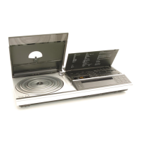
Technical specifications for the CD player, including disc types, frequency response, and SNR.
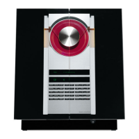
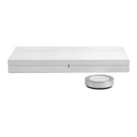
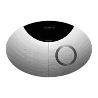
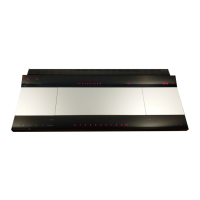
Physical dimensions, weight, and cabinet finish of the BeoSound 3000.
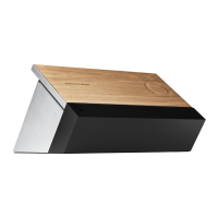
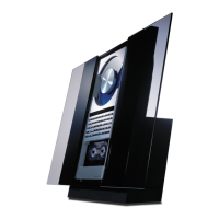
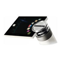
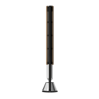
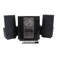
List of accessories provided with the unit, such as stands and brackets.
Details on various connection types like Master Link, Audio Aux, Power Link, and Headphones.
Wiring diagram for the transformer on PCB15 for EU, LAT, and KOR voltage models.
Wiring diagram for the transformer on PCB15 for GB and AUS 240V models.
Wiring diagram for the transformer for USA-CDN and TWN 120V models.
Wiring diagram for the transformer for Japan 100V model.
Instructions on how to tune into radio stations using the device controls.
Steps to turn on the radio and select a station.
Instructions for playing a CD, including track selection.
Guide on how to set the internal clock of the BeoSound 3000.
Instructions on operating the BeoSound 3000 using the Beo4 remote.
Procedure for programming options on the Beo4 remote control.
Explains how to read component types, coordinate systems, and wiring conventions in diagrams.
Details on component prints and coordinate systems used on PCBs.
Explanation of codes used for wiring connections within and between diagrams.
How supply voltages are indicated in the diagrams.
Description of the three different ground symbols utilized in circuit diagrams.
Explanation of the symbol for safety components and replacement guidelines.
Details on how DC voltages, oscillograms, and AC voltages are measured.
Warnings regarding laser product safety and lithium battery handling.
Wavelength and effect specifications for the CD laser diode.
Information and warnings about the lithium battery, including replacement notes.
Explanation of fuse symbols and their corresponding ampere ratings.
List and description of functional test points for the FM/AM detector circuit.
PCB layout diagram for the light and motor control module.
PCB layout diagram for the µPH8 interface module.
Reference to the diagram for the headphone section.
PCB layout diagram for the IR receiver and left door sensor.
PCB layout diagram for the right door sensor.
PCB layout diagram for the transformer module.
PCB layout diagram for the display module.
List of electrical components for the µPH8 Interface module.
List of electrical components for the µPH8 Microcomputer module.
List of electrical components for the Display module.
List of electrical components for the Light and Motor Control module.
List of electrical components for Power Supply, Input Select, and Pre-Amplifier.
List of electrical components for the Transformer module.
List of electrical components for the Headphone module.
List of electrical components for the Tuner module (FM/AM/RDS/Stereo).
List of electrical components for the CD PRO MKI Interface module.
List of electrical components for the IR receiver and left door sensor module.
List of electrical components for the Door sensor right module.
Detailed list of mechanical parts for the front of the unit, including covers, buttons, and modules.
List of mechanical parts specific to the Display module.
List of mechanical parts for the Light and Motor Control module.
List of screws, washers, and other small hardware components.
Detailed list of mechanical parts for the chassis and related components.
List of mechanical parts for the Power Supply, Input Select, and Pre-Amplifier module.
List of mechanical parts for the Tuner module.
List of mechanical parts for the Master Link Audio Interface module.
List of accessories provided with the unit, e.g., stands.
List of available language versions for the User's Guide.
List of available language versions for the Reference Book.
List and description of test modes related to the tuner functions.
General test modes for the system, covering display, keyboard, and software.
List and description of test modes specific to the CD player functionality.
Procedure for activating test modes using the device or remote control.
Automatic offset adjustment for FM tuning.
Manual offset adjustment for FM tuning.
Displays the unit's regional variant status (e.g., EU, US, JP).
Checks if the RDS radio program name is displayed correctly.
Configures tuner settings based on regional variants (EU, US, AUS).
Tests all pixels on the display by showing different characters/icons.
Tests the functionality of each key on the unit's keyboard.
Reads and displays the software version of the unit.
Displays various service counters like stand-by time and active times.
Detects and displays errors related to EEPROM, ML, IIC-bus, RS232, CD, and lids.
List of specific error codes related to EEPROM read/write operations.
List of specific error codes related to Master Link communication.
List of specific error codes related to IIC bus communication.
Error codes for serial communication issues like overrun or noise.
Error codes originating from the unit's operation system.
Error codes related to input/output driver operations.
List of specific error codes related to CD player operations.
Tests the functionality of ROM, RAM, and EEPROM.
Resets settings to default for sales purposes.
Reads out the product's item, type, and serial numbers.
Reads out the configured options for the unit.
Attempts to focus the CD laser pickup.
Turns off the CD laser pickup focus.
Initiates CD playback.
Stops CD playback.
Procedure for testing the Master Link data communication circuits.
How to measure the CD laser current and identify a defective laser head.
How to measure the eyepattern for CD system diagnostics.
Procedure for exchanging the microprocessor module, including EEPROM transfer.
Explanation of the PIN code system for theft protection.
Procedure for entering the 5-digit service code for temporary access.
Information on using and obtaining the Master Code for unlocking the system.
Procedure for exchanging the EEPROM on PCB3 and data transfer.
Procedure for exchanging both microprocessor and EEPROM, requiring pre-programming.
Explanation of how the PIN code system works and its security features.
Step-by-step guide to activate the PIN code system and set a personal code.
Steps to disable the PIN code system.
Procedure to follow if the PIN code is forgotten, involving a Master Code.
Instructions on how to change the existing PIN code, including security limits.
Steps to safely remove the glass doors from the unit.
Procedure for removing the back cover of the unit.
Instructions for removing the PCB2 and PCB3 modules.
Specific steps and warnings for removing the PCB5 module.
Detailed steps on how to conduct the insulation test correctly.
Ensures good contact for both terminals of the insulation tester to avoid damage.
Warning about carefully controlling the voltage on the insulation tester.