Replacement of modules 5.1
Replacement of modules
Modules that can be replaced
BeoVision 7 -32 in service position ............................. 5.5
Left chassis in service position .................................... 5.7
Right chassis in service position .................................. 5.8
Remove contrast screen ............................................. 5.9
Replace LCD ............................................................ 5.10
Replace 999 Module, Main chassis ........................... 5.14
Replace 997 Module, DVD Main chassis ................... 5.17
Replace 996 Module, DVD mechanism .................... 5.18
Replace 990 Module, DVB-S .................................... 5.20
Replace PCB2, Scart 3 .............................................. 5.22
Replace PCB8, Decoupling ....................................... 5.23
Replace PCB32, DSM ............................................... 5.24
Replace PCB41, Home Cinema Control .................... 5.25
Replace PCB58, Status display .................................. 5.26
Replace PCB59, Camcorder ..................................... 5.27
Replace PCB63, Modulator ...................................... 5.28
Replace PCB74, DVD supply ..................................... 5.29
Replace NTC ............................................................ 5.30
Replace fan .............................................................. 5.31
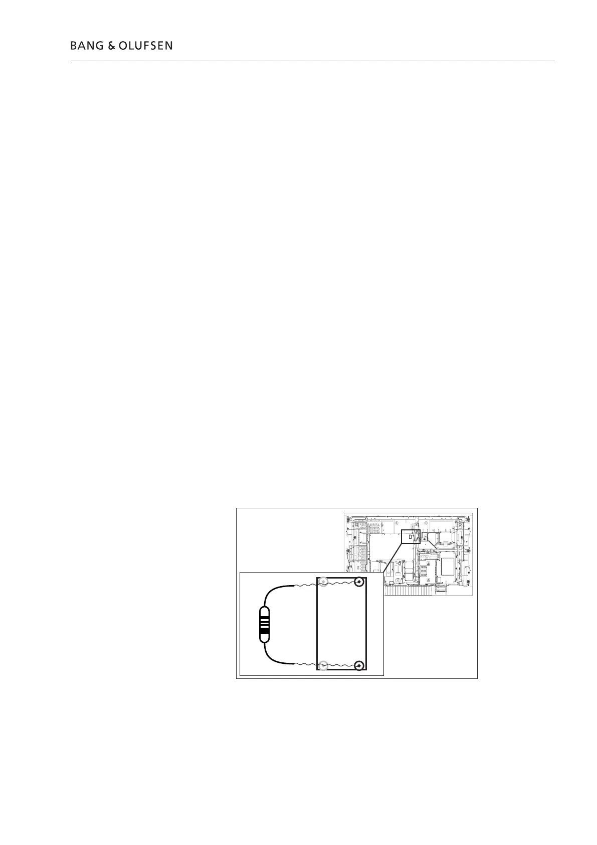
Short-circuit pin 3 and 4, LCD
power supply, as shown.
If not, you will damage the
LCD panel!
Warning – Discharge the power supply before dismantling
The power supply must be discharged before dismantling and/or replacement of
LCD, any modules or PCB’s.
There is a major risk of damaging the LCD when the connection between the LCD
and the Main chassis is disconnected and the power supply has not been discharged.
Purpose of replacement of modules
Short instructions for replacement of the available modules, with reference to
additional illustrations:
- The correct sequence for replacing modules.
- Text and illustrations.
- Reference to adjustment.
Modules that do not require any special procedure may be shown as only illustrations.
 Loading...