EasyManua.ls Logo

Banner DF-G1 Expert User Manual

Default Icon
10 pages
To Next Page IconTo Next Page
Page #1 background imageLoading...
Page #1 background image
Quick Start Guide
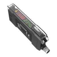
Advanced sensor with dual digital displays for use with plastic and glass fiber optic assemblies
For complete technical information about this product, including dimensions, accessories, and specifications, see
www.bannerengineering.com
and search for your model number. The instruction manual is p/n 161999.
WARNING:
Do not use this device for personnel protection
Using this device for personnel protection could result in serious injury or death.
This device does not include the self-checking redundant circuitry necessary to allow its use in
personnel safety applications. A device failure or malfunction can cause either an energized (on) or de-
energized (off) output condition.
Overview
Figure 1. DF-G1 Model Features
1 Output LED
2 LO/DO Switch
3 RUN/PRG/ADJ Mode Switch
4 Lever Action Fiber Clamp
5 Red Signal Level
6 Green Threshold
7 +/SET/- Rocker Button
Models
Model
Outputs Connector
1
DF-G1-NS-2M Single NPN
2 m (6.5 ft) cable, 4-wire
DF-G1-PS-2M Single PNP
DF-G1-KS-2M Dual outputs, 1 push-pull IO-Link and 1 PNP
(complementary outputs)
DF-G1-NS-Q5 Single NPN
150 mm (6 in) PVC pigtail, M12 Euro QD connector, 4-pin
DF-G1-PS-Q5 Single PNP
DF-G1-KS-Q5 Dual outputs, 1 push-pull IO-Link and 1 PNP
(complementary outputs)
DF-G1-NS-Q7 Single NPN
Integral M8 Pico QD connector, 4-pin
DF-G1-PS-Q7 Single PNP
DF-G1-KS-Q7
Dual outputs, 1 push-pull IO-Link and 1 PNP
(complementary outputs)
1
Connector options:
A model with a QD connector requires a mating cordset .
For 9 m cable, change the suffix 2M to 9M in the 2 m model number (example, DF-G1-NS-9M).
For 150 mm (6 in) PVC pigtail, M8 Pico QD connector, 4-pin change the suffix 2M to Q3 in the 2 m model number (example, DF-G1-NS-Q3).
DF-G1 Expert
Dual Display Fiber Amplifier
Original Document
161275 Rev. E
21 March 2019
161275

Questions and Answers:

Banner DF-G1 Expert Specifications

General IconGeneral
BrandBanner
ModelDF-G1 Expert
CategoryAmplifier
LanguageEnglish

Summary

Quick Start Guide

Overview

Provides a general overview of the DF-G1 model features with a labeled diagram.

Models

Details various DF-G1 models, their outputs, and connector options.

Installation Instructions

Mounting Instructions

Step-by-step guide for mounting the DF-G1 amplifier onto a standard DIN rail.

Installing the Fibers

Instructions for correctly inserting and securing fiber optic cables into the amplifier.

Fiber Adapters

Guidance on using fiber adapters for thin fibers to ensure a secure fit.

Wiring and Interface

Wiring Diagrams

Illustrates NPN, PNP, and IO-Link wiring configurations for the DF-G1 amplifier.

Top Panel Interface Overview

Introduces the top panel interface, listing its components and functions.

Operating Instructions

Top Panel Controls

Details the function of the RUN/PRG/ADJ switch, LO/DO switch, and rocker button.

Run Mode Operation

Explains the operation and limitations of the sensor in Run Mode.

Program Mode

Program Mode Settings

Outlines the settings that can be programmed via the display-driven menu.

Factory Default Settings

Lists the default values for various programmable settings.

Adjust Mode and TEACH Procedures

Adjust Mode

Allows manual adjustment of thresholds and expert TEACH/SET methods.

TEACH Procedures Overview

Lists the various TEACH procedures available for sensor setup.

Two-Point TEACH Method

Details the Two-Point TEACH method for establishing a single switching threshold.

Dynamic TEACH Method

Explains the Dynamic TEACH method for on-the-fly learning of sensing conditions.

Advanced SET Methods

Window SET

Describes setting window thresholds with programmable offsets.

Light SET

Sets a threshold offset below the presented condition for darker targets.

Dark SET

Sets a threshold offset above the presented condition for lighter targets.

Calibration and Troubleshooting

Calibration SET Method

Sets a threshold exactly at the presented condition for precise detection.

Troubleshooting Alerts

Explains manual adjustment disable states and TEACH/SET result interpretations.

Specifications

Threshold Alert or Error States

Describes states indicating issues with threshold optimization and corrective actions.

Sensing Beam and Power Specs

Details sensing beam properties, supply voltage, current consumption, and output ratings.

Connections, Interface, and Controls

Covers cable types, IO-Link, indicators, and manual adjustment controls.

Factory Default Settings

Lists the default values for various programmable settings.

Safety and Compliance

Required Overcurrent Protection

Details the necessary overcurrent protection requirements based on supply wiring gauge.

Environmental Rating and Conditions

Lists the recommended operating and storage temperature and humidity ranges.

Certifications and Warranty

Lists product certifications and outlines the manufacturer's limited warranty terms.

Related product manuals