The single-channel hookup configuration cannot detect short circuits to secondary sources of +24V dc or detect the
loss of the switching function of the safety input device (that is, it is not redundant) and thus this circuit typically can meet
only ISO 13849-1 Category 2.
It is recommended that in all circumstances the installation of the Safety Module and its associated safety input devices
are installed to eliminate or minimize the possibility of failures and faults that could result in the loss of the safety
function(s). Methods to eliminate or minimize the possibility of these failures include, but are not limited to:
• Physically separating interconnecting control wires from each other and from secondary sources of power.
• Routing interconnecting control wires in separate conduit, runs, or channels.
• Locating all elements (modules, switches, and devices under control) within one control panel, adjacent to each
other, and directly connected with short wires.
• Properly installing multi-conductor cabling and multiple wires through strain-relief fittings. (Over-tightening of a
strain-relief can cause short circuits at that point.)
• Using positive-opening components as described by IEC 60947-5-1 that are installed and mounted in a positive
mode.
• Periodically checking the functional integrity / safety function and training operators, maintenance personnel, and
others associated with the operation of the machine to recognize and immediately correct such failures.
If you have any questions about your intended use, please contact a Banner applications engineer.
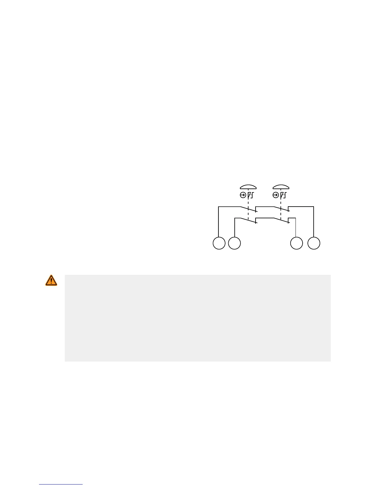
Connection of Multiple Switches
Connect the poles of multiple switches, such as e-stop switches, as
shown in the figure at right. The switches are shown in the "armed"
position with both contacts closed. Multiple switches connected to
one Safety Module must be series connected (see figure at right
and the warning, Multiple Switching Devices).
S12S22S11 S21
E-Stop E-Stop
Figure 2. Series Connection of Multiple E-stop Switches
WARNING: Multiple Switching Devices
Whenever two or more devices are connected to the same safety module (controller):
• Contacts of the corresponding pole of each switch must be connected together in
series. Never connect the contacts of multiple switches in parallel. Such a parallel
connection defeats the switch contact monitoring ability of the Module and creates an unsafe
condition which may result in serious injury or death.
• Each device must be individually actuated (engaged), then released (or re-armed) and
the safety module reset. This allows the module to check each switch and its wiring to detect
faults.
This check must be performed during the prescribed checkouts. Failure to test each device
individually in this manner may result in undetected faults and create an unsafe condition
which may result in serious injury or death.
ES-FA-9AA and ES-FA-11AA E-Stop Safety Module
P/N 60606 Rev. G www.bannerengineering.com - Tel: +1-763-544-3164 5
 Loading...