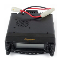
Do you have a question about the BAOJIE BJ-9900 and is the answer not in the manual?
| Power Output | 25W/10W/5W |
|---|---|
| Channel Capacity | 200 |
| Operating Voltage | 13.8V DC ±15% |
| Frequency Range | 400-470MHz |
| Channel Spacing | 25 kHz |
Provides necessary technical information for the maintenance and inspection of mobile radio BJ-9900.
Safety tips for personal protection during operation and maintenance of the radio equipment.
Details the signal path for receiving VHF and UHF signals, including mixers and IF stages.
Describes the squelch control mechanism for both main and sub bands.
Explains the signal path for transmitting VHF and UHF signals, including modulation and power amplification.
Explains the circuit responsible for maintaining stable output power during transmission.
Describes the Push-To-Talk (PTT) electrical circuit operation.
Details the Phase-Locked Loop (PLL) circuitry for frequency synthesis.
Block diagram of the Transmit-Receive unit, showing key functional blocks.
Block diagram of the Display Unit, illustrating its components and connections.
Block diagram of the Panel-Sub Unit, detailing its functional blocks.
Block diagram for the Volume/Squelch Left/Right unit.
Detailed schematic diagram for the Display Unit.
Physical layout of components on the Display Unit PCB.
List of components used in the Display Unit with their specifications.
Detailed schematic diagram for the TX-RX Unit.
Physical layout of components on the TX-RX Unit PCB.
List of components used in the TX-RX Unit.
Physical layout of components on the Panel Unit PCB.
Detailed schematic diagram for the Panel-Sub Unit.
Physical layout of components on the Panel-Sub Unit PCB.
List of components used in the Panel-Sub Unit.
Detailed schematic diagram for the VR-L/R Unit.
Physical layout of components on the VR-L/R Unit PCBs.
List of components used in the VR-L/R Unit.
Overall technical specifications including frequency range, modulation, and dimensions.
Detailed output power, modulation type, and spurious radiation for transmission.
Detailed sensitivity, selectivity, and audio output specifications for reception.
 Loading...