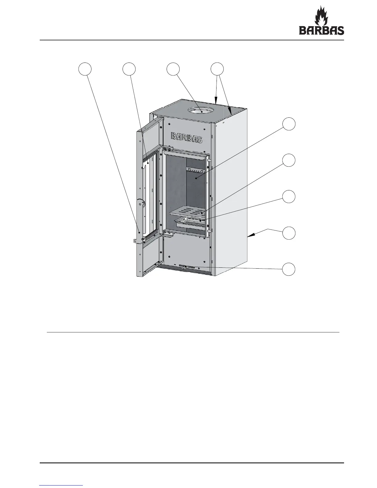
Figure 3: Operation ECO 90 / ECO 100
1 2
3
4
5
6
7
9
8
1 Handle
2 Ceramic heat-proof glass
3 Smoke (ue gas) outlet Ø150 mm (top connection)
4 Convection air escape opening (permanent)
5 Side panels (vermiculite plate) / Inner lining
6 Grate / Primary air-supply
7 Ashtray
8 Intake openings combustion air and convection air (rear of appliance)
9 Combustion air-supply slider (One combined operation for adjusting all three
air supplies! Primary, Secondary and Tertiary)