Manual 2100-581D
Page 2 of 26
CONTENTS
Figures
Figure 1 Fresh Air Damper Assembly.................... 5
Figure 2 Unit Dimensions ................................... 7
Figure 3A
Mounting Instructions – W17, 18, 24 .......... 8
Figure 3B
Mounting Instructions – W30, 36 ............... 9
Figure 3C
Mounting Instructions – W42, 48, 60, 70 ..10
Figure 4 Electric Heat Clearance ....................... 11
Figure 5 Wall Mounting Instructions .................. 12
Figure 6 Wall Mounting Instructions .................. 12
Figure 7 Common Wall Mounting Installations .... 13
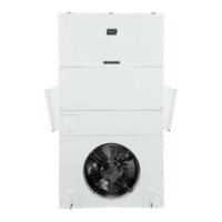
Figure 8 Fan Blade Setting ............................... 18
Tables
Table 1 Fan Blade Dimensions ......................... 18
Table 2 Cooling Pressure ................................. 19
Table 3 Electrical Specifications W**A ............. 20
Table 4 Electrical Specifications W**L .............. 21
Table 5 Recommended Airflow ......................... 22
Table 6 Indoor Blower Performance .................. 22
Table 7 Maximum ESP Electric Heat Only ......... 22
Table 8 Electric Heat ...................................... 23
Table 9A Optional Accessories
– Right Hand ....... 24
Table 9B Optional Accessories
– Left Hand .............25
Table 10 Vent and Control Options .........................26
Getting Other Information and Publications .... 3
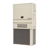
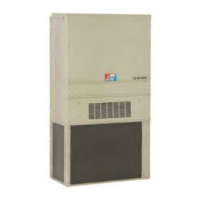
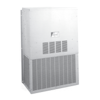
Wall Mount General Information ......................... 4
Air Conditioner Wall Mount Model Nomenclature ..... 4
Shipping Damage ................................................. 4
General ............................................................... 4
Duct Work ........................................................... 5
Filters ................................................................. 5
Fresh Air Intake ................................................... 5
Condensate Drain ................................................ 5
Installation ............................................................... 6
Wall Mounting Information .................................... 6
Mounting the Unit ................................................ 6
Clearances Required ............................................. 6
Minimum Clearances ............................................ 6
Wiring – Main Power ........................................... 14
Wiring – Low Voltage ........................................... 14
Start Up ................................................................... 15
General ............................................................. 15
Topping Off System Charge ................................. 15
Safety Practices ................................................. 15
Important Installer Note ...................................... 16
High Pressure Switch .......................................... 16
Three Phase Scroll Compressor ............................ 16
Phase Monitor .................................................... 16
Condenser Fan Operation .................................... 16
Service Hints ..................................................... 16
Sequence of Operation ........................................ 16
Compressor Control Module ................................. 17
Pressure Service Ports ........................................ 17
Service ..................................................................... 18
Fan Blade Setting Dimensions ............................. 18
R-410A Refrigerant Charge ................................. 18
Removal of Fan Shroud ....................................... 18