Manual 2100-581B
Page 7 of 26
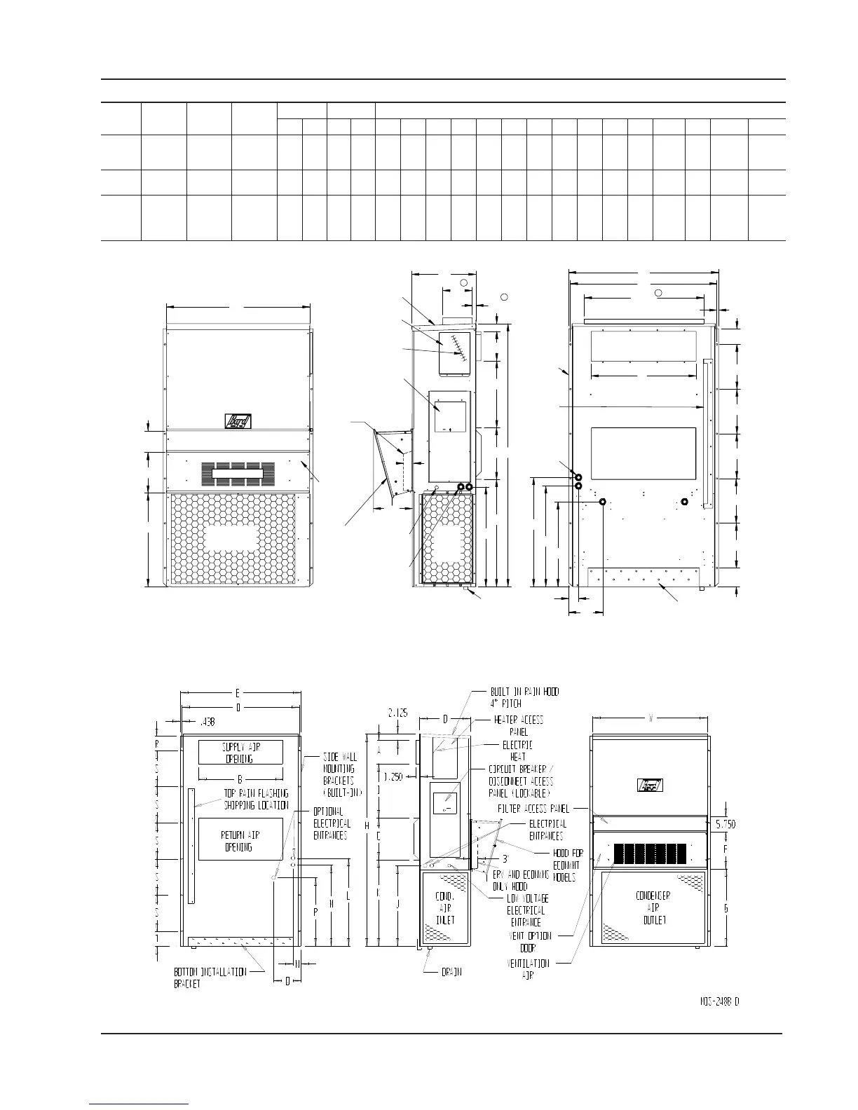
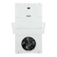
Dimensions of Basic Unit for Architectural and Installation Requirements (Nominal)
MODEL
WIDTH
(W)
DEPTH
(D)
HEIGHT
(H)
SUPPLY RETURN
A B C B E F G I J K L M N O P Q R S T
W17A, L
W18A, L
W24A, L
33.300 17.125 70.563 7.88 19.88 11.88 19.88 35.00 11.00 25.75 20.56 26.75 28.06 29.25 27.00 2.63 34.13 22.06 10.55 4.19 12.00 5.00
W30A, L
W36A, L
38.200 17.125 70.563 7.88 27.88 13.88 27.88 40.00 11.00 25.75 17.93 26.75 28.75 29.25 27.00 2.75 39.19 22.75 9.14 4.19 12.00 5.00
W42A, L
W48A, L
W60A, L
W70A, L
42.075 22.432 84.875 9.88 29.88 15.88 29.88 43.88 13.63 31.66 30.00 32.68 26.94 34.69 32.43 3.37 42.88 23.88 10.00 1.44 16.00 1.88
3"
11"
7.88
1.00
31.88
Heat
models.
Electric
Hood for
ECONWMT
MIS-2487 G
1
1
1
Condenser
Filter Access Panel
Front View
Air Outlet
Standard
flush vent
door for
non-ERV/
Econ.
models
Ventilation Air
5.88
F
W
G
Low Voltage
Electrical
Entrance
High Voltage
Side View
Drain
Electrical
Cond.
Air
Inlet
Heater
Access
Panel
4° Pitch
Built In
Rain Hood
Disconnect
Access Panel
(Lockable)
Entrance
C. Breaker/
Hood for ERV and
ECONWMS models
only
C
I
D
J
H
A
2.13
K
Mounting
Supply Air Opening
Side Wall
Brackets
Location
Shipping
Return Air Opening
(Built In)
Optional
Electrical
Entrances
Top Rain
Flashing
Bottom Installation
Bracket
Back View
P
M
O
E
R
S
S
S
S
S
T
.44
N
Q
B
L
j Optional top outlet (factory installed only) for W30A and W36A models only.
FIGURE 2
All dimensions are in inches. Dimensional drawings are not to scale.
W**A
RIGHT
UNIT
W**L
LEFT
UNIT