Manual 2100-200
Page 4
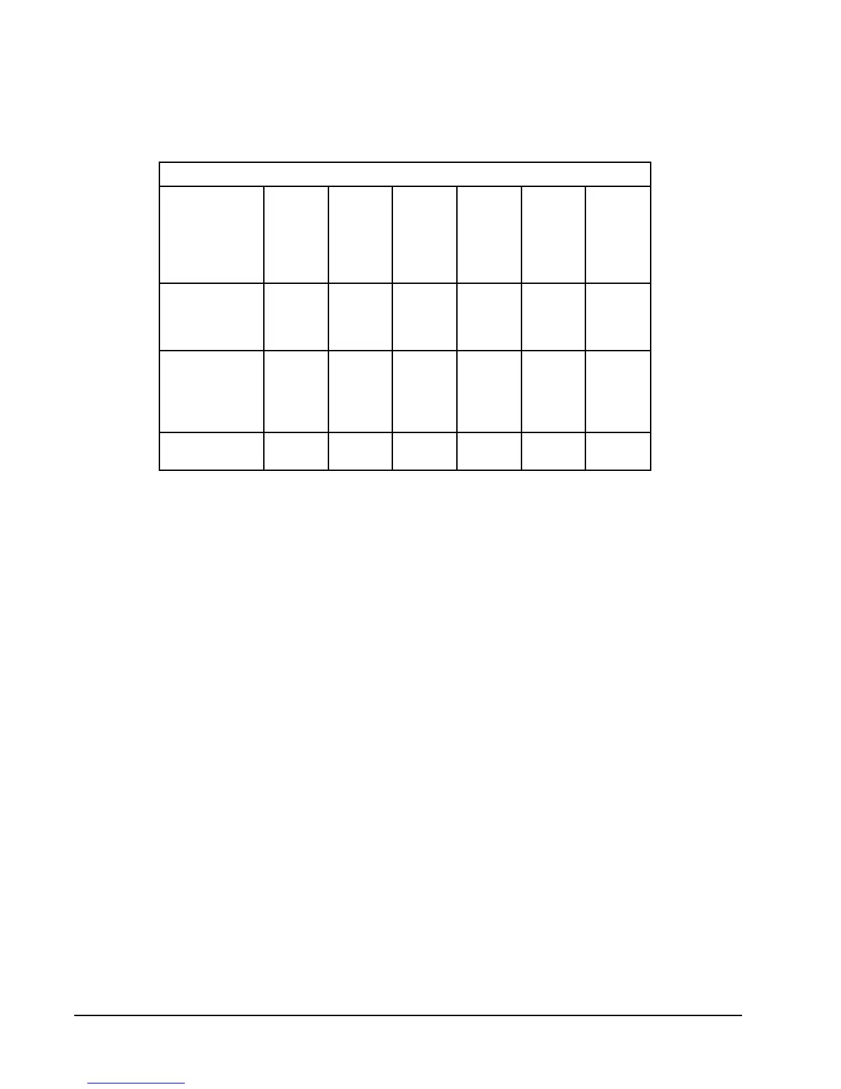
TABLE 2
ELECTRICAL SPECIFICATIONS
TIUCRICELGNIS
ledoM
detaR
&stloV
esahP
.oN
dleiF
rewoP
stiucriC
muminiM
tiucriC
yticapmA
mumixaM
lanretxE
roesuF
tiucriC
rekaerB
dleiF
rewoP
eziSeriW
dnuorG
eziSeriW
Z0A,00A-181AW
50A
80A
01A
1-802/032
1
1
1
1
61
03
54
65
02
03
54
06
21
01
8
6
21
01
01
01
Z0A,00A-142AW
40A
50A
80A
01A
1-802/032
1
1
1
1
1
71
42
03
54
65
02
52
03
54
06
21
01
01
8
6
21
01
01
01
01
Z0B,00B-142AW
60B
3-802/032
1
1
31
22
51
52
41
01
21
01
S
Q
R
Maximum size of the time delay fuse or HACR type circuit breaker for protection of field wiring
conductors.
Based on 75° copper wire. All wiring must conform to the National Electrical Code and all
local codes.
These "Minimum Circuit Ampacity" values are to be used for sizing the field power conduc-
tors. Refer to the National Electric Code (latest revision), Article 310 for power conductor
sizing.
CAUTION: When more than one field power conductor circuit is run through one
conduit, the conductors must be derated. Pay special attention to note 8 of table 310
regarding Ampacity Adjustment Factors when more than three conductors are in a raceway.
Q
R
RS
 Loading...