Manual 2100-385B
Page 16
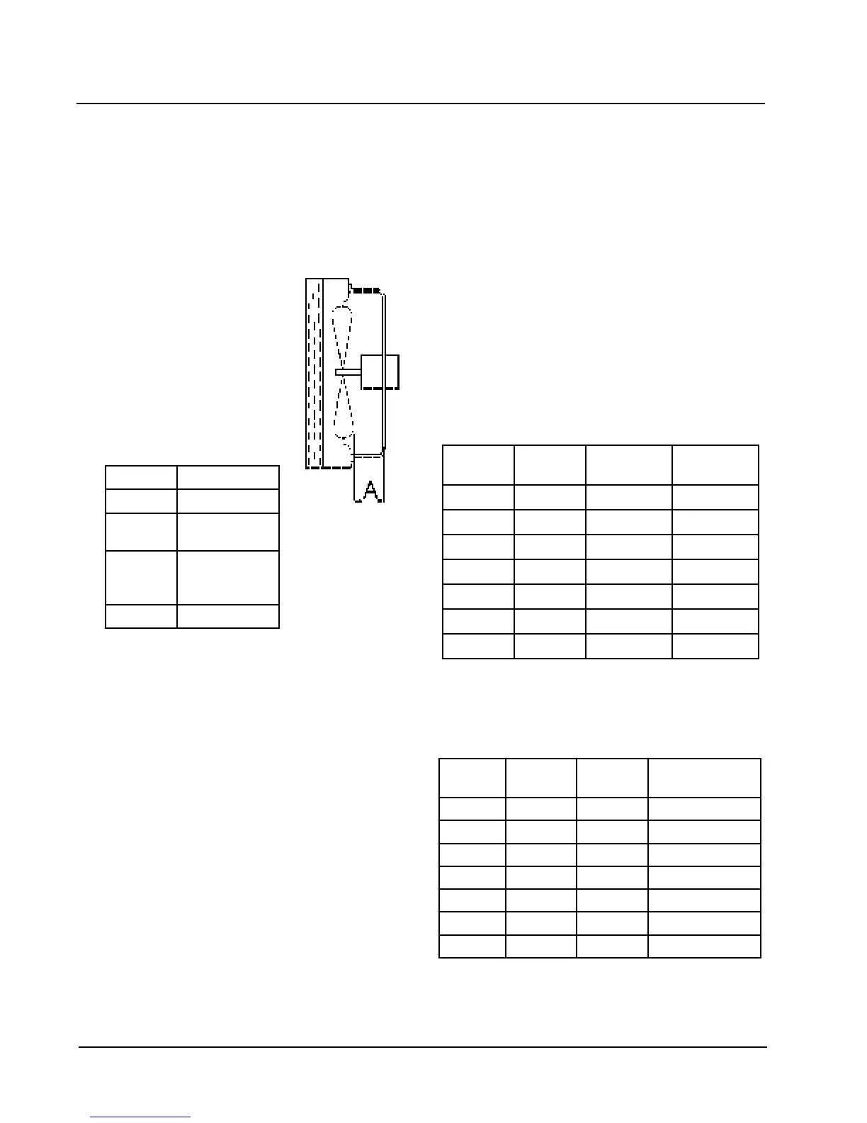
FAN BLADE SETTING DIMENSIONS
Shown in Figure 9 is the proper method to measure the
fan blade location.
Any service work requiring removal or adjustment in the
fan and/or motor area will require that the fan blade
location be checked.
FIGURE 9
FAN BLADE SETTING
TROUBLESHOOTING
REMOVAL OF FAN SHROUD
1. Disconnect all power to unit.
2. Remove the screws holding both grilles – one on
each side of unit – and remove grilles.
3. Remove screws holding fan shroud to condenser and
bottom – 9 screws.
4. Unwire condenser fan motor.
5. Slide complete motor, fan blade, and shroud
assembly out the left side of the unit.
6. Service motor/fan as needed.
7. Reverse steps to reinstall.
TABLE 5
FAN BLADE DIMENSIONS
ledoMAnoisnemiD
252EW0.1
103EW
173EW
52.1
124EW
284EW
206EW
57.1
107EW52.1
REFRIGERANT CHARGE
The system is charged with R-407C. The correct
quantity is shown on the unit rating plate. Optimum unit
performance will occur with a refrigerant charge
resulting in a suction line temperature (6 inches from
compressor) as shown in Table 6.
The suction line temperatures shown in Table 6 are
based upon 80°F dry bulb / 67°F wet bulb (50 percent
R.H.) temperature and rated airflow across the
evaporator coil during cooling cycle.
See page 20 for instructions in servicing units which
contain refrigerant R-407C
TABLE 6
SUCTION LINE TEMPERATURES
ledoM
detaR
wolfriA
59
o
F
.pmeTDO
28
o
F
.pmeTDO
252EW57606-8576-56
103EW05966-4686-66
173EW000195-7506-85
124EW051175-5507-86
284EW572195-7517-96
206EW004185-6556-36
107EW584136-1626-06
TABLE 7
RATED CFM and ESP
ledoM
detaR
MFC
detaR
PSE
dednemmoceR
egnaRwolfriA
252EW57622.057-016
103EW05922.5401-558
173EW000102.0011-009
124EW561103.0821-0501
284EW572102.0041-0511
206EW004103.0451-0621
107EW584102.0361-0431
RATED CFM AND RATED ESP WITH BLOWER
SET ON HIGH SPEED.