61-101-00802.EF1 Revision J Page | 30
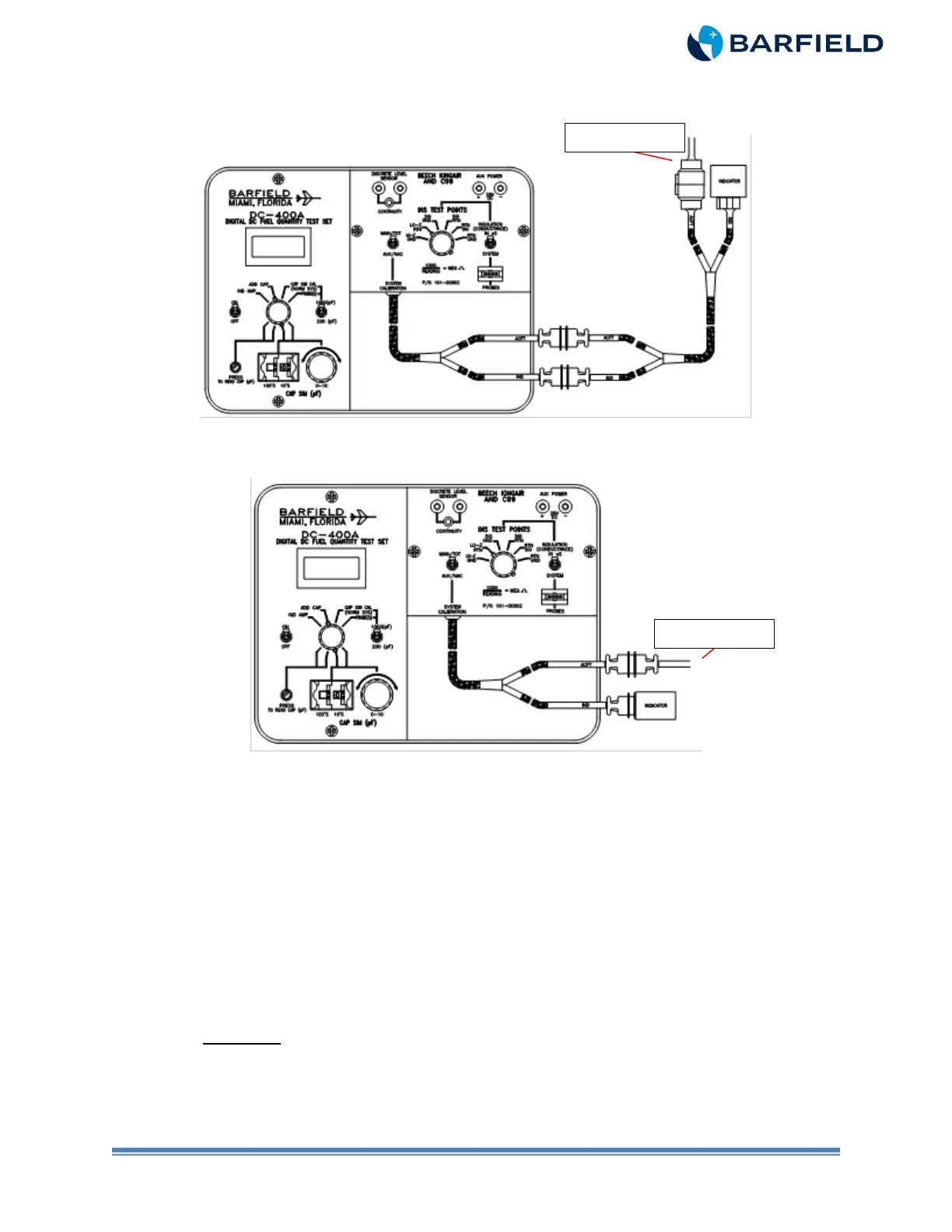
Note: Figure 11 depicts using Adapter Cable 101-00831 for conversion to systems
with circular style connectors.
Figure 11 Alternate Calibration (with 101-00831 Adapter)
Figure 12 Alternate Calibration
D. Test
(1) Set the T/S ON / OFF switch to ON.
(2) Set the CAP SIM (pF) 100’s and the 10’s thumbwheels to the digits necessary to
adjust the T/S display to a MAIN / TOTAL EMPTY nominal value listed in Table 2
for the aircraft under test.
(3) Press and hold the PRESS TO READ CAP (pF) pushbutton while adjusting the
CAP SIM (pF) control knob to obtain a T/S reading for the aircraft as per Table 2.
(4) Close the circuit breakers.
(5) Connect the aircraft battery and turn the battery switch to ON.
(6) Rotate the TEST FUNCTION switch to IND AMP.
CAUTION: DO NOT TAP BEZEL OF INSTRUMENT TO VIBRATE. TO REMOVE
FRICTION, GENTLY TAP ADJACENT PANEL OR REAR HOUSING OF
INDICATOR BEFORE TAKING READINGS.
(7) Verify the aircraft indicator shows a reading slightly below zero (approximately one
needle width).