61-101-00802.EF1 Revision J Page | 26
E. Disconnecting/Reconfiguring
(1) Disconnect the test leads from the DISCRETE LEVEL SENSOR.
(2) Disconnect the test leads from the T/S.
2. INDICATOR BENCH TEST
Note: Refer to Precautions and Preliminary in General Information section.
Note: Failure to calibrate the system after performing the indicator bench test will result in
an inaccurate fuel quantity reading.
A. Test Set Preparation
(1) Set the ON/OFF switch to OFF.
(2) Rotate the TEST FUNCTION switch to CAP SIM CAL (NORM SYS).
(3) Set the INSULATION / SYSTEM switch to SYSTEM.
(4) Set the MAIN / TOT-AUX / NAC switch to MAIN / TOT.
(5) Set the 200 (pF) / 1000 (pF) switch to 200 (pF).
B. Connecting Test Set
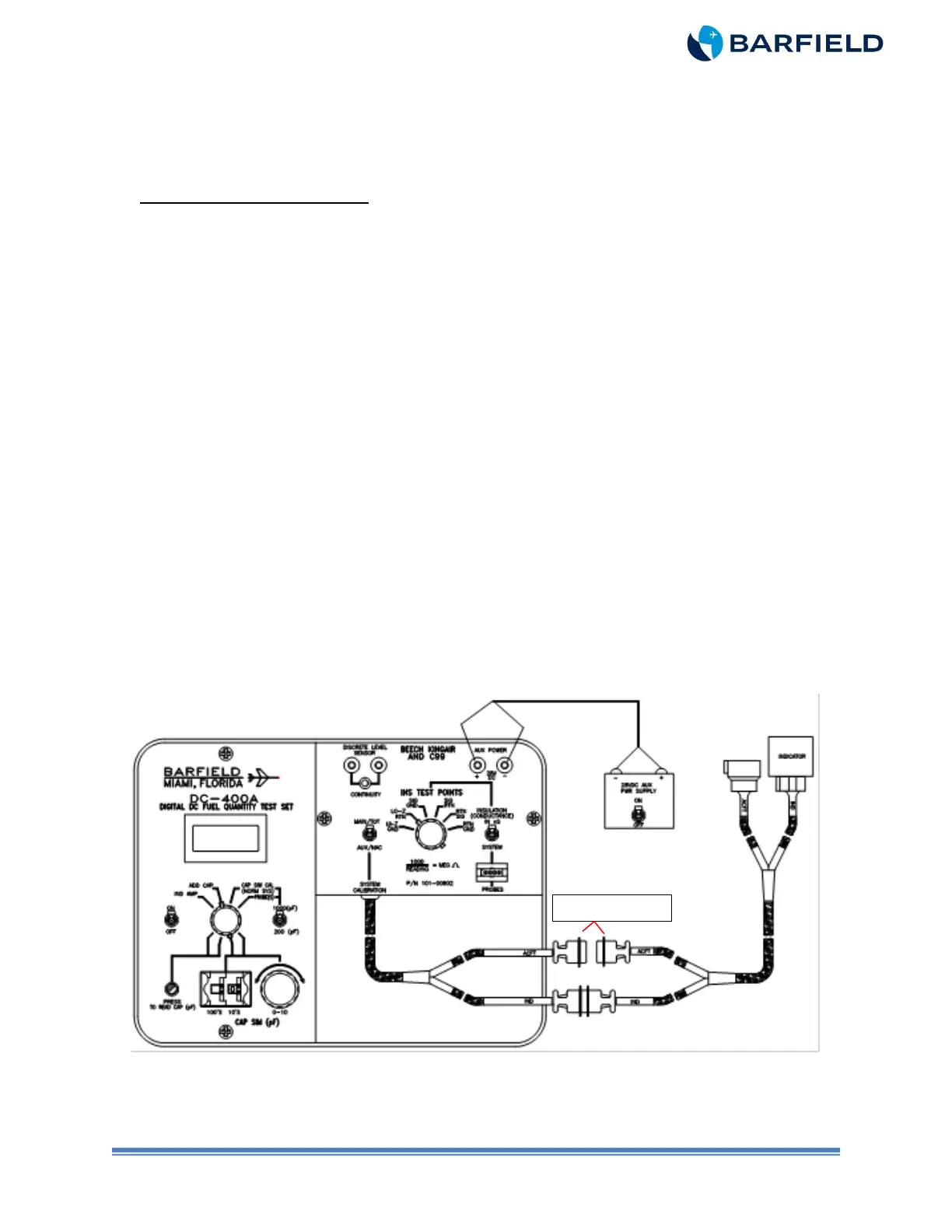
(1) Connect T/S as shown in either Figure 9 or Figure 10.
Note: Figure 9 depicts using Adapter Cable 101-00831 for conversion to systems
with circular style connectors.
(2) Connect T/S IND connector to Indicator.
(3) Do NOT connect T/S ACFT connector.
(4) Connect the 28 VDC power supply to the T/S AUX POWER jacks using Banana to
Banana leads P/N 101-01010. Observe polarity.
Figure 9 Indicator Bench Test (with 101-00831 Adapter)