61-101-00802.EF1 Revision J Page | 21
CHAPTER 2: ALTERNATE TESTS
1. PROBES BENCH TEST
Note: Refer to Precautions and Preliminary in General Information section.
A. Test Set Preparation
(1) Set the T/S ON / OFF switch to OFF.
(2) Rotate the TEST FUNCTION switch to PROBE(S).
(3) Set the INSULATION / SYSTEM switch to SYSTEM.
(4) Set the MAIN / TOT-AUX / NAC switch to MAIN / TOT.
(5) Set the 200 (pF) / 1000 (pF) switch to 200 (pF).
B. Connecting Test Set
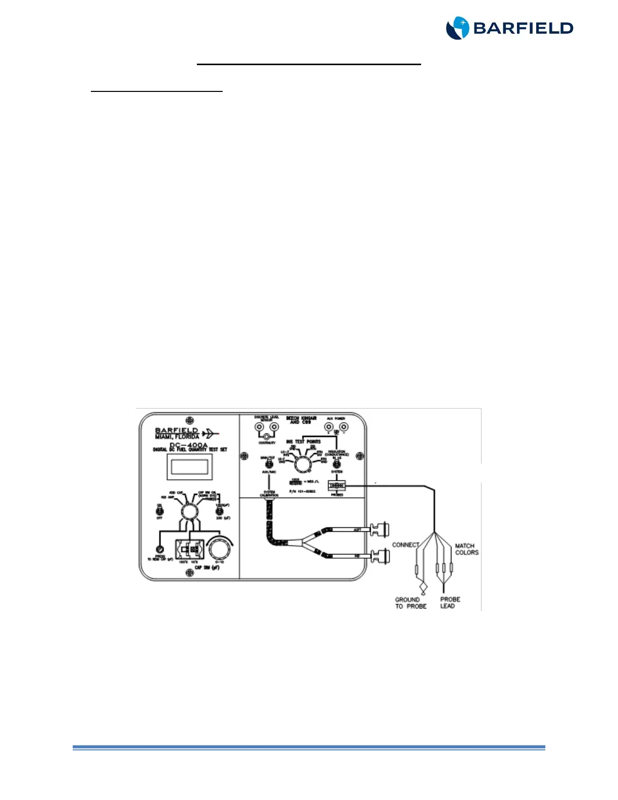
(1) Connect the T/S to the probe as depicted in Figure 7.
(2) Connect the probe adapter, P/N 101-00829 or P/N 101-00814, to the T/S PROBES
receptacle as shown per Figure 7.
(3) Determine the part number and physical makeup of the probe under test.
(4) Connect the color-coded wires (sockets) from the probe adapter to the matching
color of the probe lead wires (pins).
(5) Connect the socket pin ground lead of the probe adapter (small black lead) to the
ground clip pigtail of the probe adapter. Attach the ground clip to the grounding area
on the probe.
Figure 7 Bench Probe Interface
C. Test
(1) Set the T/S ON / OFF switch to ON.
(2) Press the PRESS TO READ CAP (pF) pushbutton to display probe capacitance.
(3) Verify probe capacitance is within the tolerance referenced in Table 5 through Table
8 for Empty or Tables 9 through 12 for Full.