5 Installation/Commissioning
Only install or uninstall the switch when deenergized (electrically and
hydraulically/pneumatically).
Pressure connection and electrical connection must be carried out by trained or instructed
personnel according to state-of-the-art standards.
The switch must only be installed in systems where the maximum pressure P
max
is not
exceeded (see type label).
Alternating pressure - vacuum applications are not authorized in switch types which are
suitable for both vacuum and pressure applications.
Pressure peaks and pressure shocks exceeding the maximum operating pressure are
inadmissible.
The maximum operating pressure is the upper final value of the adjustable range or, if
specified, the pressure indicated as maximum operating pressure. Exceeding the max.
operating pressure affects the performance and the life span of the product and may
damage it.
Pressure switches must be mounted vibrationless.
Check the switch regularly for functioning.
If the switch does not work properly, stop operation immediately!
All pressure switches are tested for proper functioning before they leave the factory. The
factory proof pressures are stated on the type label.
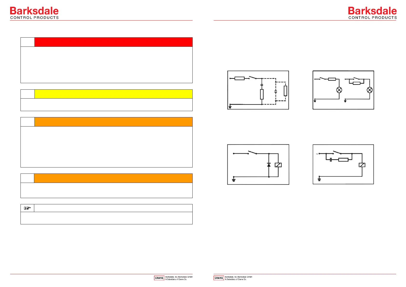
Contact Protection
The micro switches used are normally suitable for both direct and alternating current
operation. Inductive, capacitive and lamp loads may, however, considerably reduce the life
expectancy of a micro switch and, under extreme circumstances, even damage the
contacts.
Depending on the application spark suppression and current limiting is recommended (see
succeeding figures).
Fig. 1: Protection in case of capacitive
loads R1: Protection against
starting current rushes R2,R3:
Protection against high discharge
currents
Fig. 2: Lamp load provided with resistance
in parallel or series connection to
switch of condensators
Fig. 3: Protection in case of continuous
current and inductive load by
recovery diode
Fig. 4: Protection in case of alternating
current and inductive load by RC-
link
 Loading...