EasyManua.ls Logo

Barksdale ML1H - User Manual

Barksdale ML1H
8 pages
Print Icon
To Next Page IconTo Next Page
Loading...
ATEX Type Certification marking for type L1X-EX, T1X-EX, T2X-EX
Type of protection "d" explosion-proof enclosure
Approval:
II 2 G D
Ex d IIC T6
Ex tD A21 IP65 T80°C
-40°C <
Tamb < +75°C
Certificate no.: ISSEP08ATE024X
Standards applied: IEC 60079-0, IEC60079-1, IEC 61241-0 and
IEC 61241-1
L1X, T1X, T2X Models are UL (File No. E58658, Guide No. XBDV) & CSA (File No.
LR34556, Guide 400-E, Class 4868) are Listed as Temperature Indicating and Regulating
Equipment for use in Hazardous Locations, as follows;
Class I, Groups B (UL Only), C & D, Class II, Groups E, F & G, Class III.
ML1H, MT1H, L2H, T2H Models are UL (File No. E56247) & CSA (File No. LR34555,
Guide 400-E-O, Class 4813) are Listed as Temperature Indicating and Regulating
Equipment for use in Ordinary Locations.
Operating life time
The switches are designed for an operating life time of at least 1 million cycles when used
under normal design criteria.
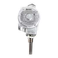
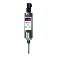
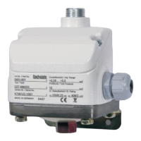
Operating Instructions Mechanical Temperature Switches
ML1H,MT1H,L2H,T2H,L1X/L1X-EX,T1X/T1X-EX,T2X/T2X-EX
1 Intended Applications....................................................................................................2
2 Safety Instructions .........................................................................................................2
3 Standards........................................................................................................................3
4 Warranty/Guaranty .........................................................................................................3
5 Transport/Storage ..........................................................................................................3
6 Installation/Commissioning...........................................................................................4
7 Maintenance/Cleaning....................................................................................................8
8 Technical Data ................................................................................................................8
Barksdale, Inc.
3211 Fruitland, Ave.
Los Angeles, CA 90058
Phone: 800 835-1060
Fax: 323 589-3463
email: sales@barksdale.com
Internet: www.barksdale.com
1
16
Bulletin No. 272182-E
Date: 07-20-2009
Specifications are subject to changes
without notice!
Buy: www.ValinOnline.com | Phone 844-385-3099 | Email: CustomerService@valin.com
Question and Answer IconNeed help?

Do you have a question about the Barksdale ML1H and is the answer not in the manual?

Overview

This document provides operating instructions for Barksdale Mechanical Temperature Switches, including models ML1H, MT1H, L2H, T2H, L1X/L1X-EX, T1X/T1X-EX, and T2X/T2X-EX.

Function Description

Barksdale temperature switches are designed for monitoring and controlling operations by detecting maximum or minimum temperatures. A micro switch within the device triggers an electrical signal when a predefined temperature threshold is reached. These switches are suitable for both direct and alternating current operation.

Important Technical Specifications

ATEX Type Certification (for L1X-EX, T1X-EX, T2X-EX):

  • Type of protection: "d" explosion-proof enclosure
  • Approval: II 2 GD, Ex d IIC T6, Ex tD A21 IP65 T80°C
  • Ambient Temperature Range: -40°C to +75°C
  • Certificate No.: ISSEP08ATE024X
  • Standards Applied: IEC 60079-0, IEC 60079-1, IEC 61241-0, IEC 61241-1

UL & CSA Listings:

  • L1X, T1X, T2X Models: UL File No. E58658 (Guide No. XBDV) & CSA File No. LR34556 (Guide 400-E, Class 4868). Listed for temperature indicating and regulating equipment in hazardous locations: Class I (Groups B (UL Only), C & D), Class II (Groups E, F & G), Class III.
  • ML1H, MT1H, L2H, T2H Models: UL File No. E56247 & CSA File No. LR34555 (Guide 400-E-O, Class 4813). Listed for temperature indicating and regulating equipment in ordinary locations.

Operating Life Time:

  • The switches are designed for an operating life of at least 1 million cycles under normal design criteria.

Measuring Ranges (Local Mount Temperature Switches):

  • Order Codes 201, 202, 203: Max. temperature at sensor -100°F to +250°F. Adjustment ranges from -49°F to +200°F.
  • Order Codes 351, 354: Max. temperature at sensor -100°F to +401°F. Adjustment ranges from 100°F to +350.6°F.
  • Order Code 454: Max. temperature at sensor -0.4°F to +500°F. Adjustment range 150.8°F to +449.6°F.

Measuring Ranges (Temperature Switch with Remote Sensor):

  • Order Code 154: Max. temperature at sensor -100°F to +200°F. Adjustment range -49°F to +151°F.
  • Order Code 251: Max. temperature at sensor -100°F to +300°F. Adjustment range 50°F to +250°F.
  • Order Code 351: Max. temperature at sensor -100°F to +401°F. Adjustment range 151°F to +350°F.
  • Order Codes 601, 603: Max. temperature at sensor -0.4°F to +650°F. Adjustment ranges from 300°F to +600°F.

Reset Values (Approximate Hysteresis):

  • GH, H micro switches: Hysteresis ranges from 1-2.8°F (for 201-354) to 2.8-6°F (for 454).
  • J micro switches: Hysteresis ranges from 2.2-4°F (for 201-354) to 2.8-5°F (for 454).
  • M micro switches: Hysteresis ranges from 1-4°F (for 201-354) to 4-6.8°F (for 454).
  • S adjustable micro switches: Hysteresis ranges from 6-20°F (for 201-354) to 10-30°F (for 454).
  • G micro switches:* Fixed hysteresis of 5.0°F.
  • For gaseous media, hysteresis will be approximately double these values.

Electrical Ratings (Micro Switch Types):

  • H (Small hysteresis, high AC/low DC loads): 125/250/480 VAC (10A Ind./Res.), 6/24 VDC (0.5A Ind./Res.).
  • M (Medium hysteresis, high AC and DC loads): 125/250/480 VAC (10A Ind./Res.), 12/24/250 VDC (5.0/1.0/0.25A Ind., 15.0/2.0/0.4A Res.).
  • GH (Small hysteresis, low voltage/low current, gold plated contacts): 125 VAC (1A Ind./Res.), 24 VDC (1A Ind./Res.). Recommended for low voltage/power applications.
  • S (Adjustable hysteresis): 125/250/480 VAC (15A Ind./Res.), 12/24/250 VDC (10.0/5.0/0.03A Ind., 15.0/6.0/0.2A Res.).
  • J (Small hysteresis, sealed): 125/250/480 VAC (10A Ind./Res.), 6/24 VDC (0.5A Ind./Res.).
  • G...RD (Manual reset): 125/250/480 VAC (10A Ind./Res.), 12/24/250 VDC (15.0/10.0/0.20A Ind., 15.0/15.0/0.3A Res.).
  • Data valid for non-explosive atmospheres. Pre-fuse of maximum current rating recommended.

Temperature Sensing Element:

  • Can be used up to 21 bar. For pressures higher than 21 bar, a suitable thermowell must be provided.

Usage Features

Intended Applications:

  • Monitoring and controlling operations based on maximum or minimum temperatures.
  • Not designed as the sole safety-relevant element in pressurized systems according to DGR 97/23/EC.

Safety Instructions:

  • Installation and uninstallation must only occur when the device is de-energized (electrically and hydraulically/pneumatically).
  • Process and electrical connections must be performed by trained personnel according to state-of-the-art standards.
  • The switch must be installed in systems where the maximum temperature Tmax (indicated on the type label) is not exceeded.
  • The temperature and pressure values, and electrical rating must remain within specified limits.
  • Observe national safety instructions for assembly, commissioning, and operation.
  • Casing surface may become very hot during operation at higher temperatures.
  • If sensor or ambient temperature limits are exceeded, the switch's function cannot be guaranteed, and damage may occur.
  • Regularly check switch operation; stop operation immediately if it malfunctions.

Set Point Adjustment:

  • The set point is adjusted by turning the adjustment knob. Visual indication on the knob is for reference only.
  • For some models, the housing cover must be removed to access the adjustment knob.
  • To adjust, heat the switch to the desired switching temperature and turn the knob to actuate the micro switch.
  • Precise adjustment for increasing temperature: Connect a control unit (lamp, buzzer) to C (common) and NO (normally open). Adjust the knob while the temperature is rising (approx. 2°C/minute) until the control unit activates. Readjust if necessary for 3-5% accuracy of the scale value.
  • Precise adjustment for decreasing temperature: Connect a control unit to C (common) and NC (normally closed). Adjust the knob. Increase temperature (approx. 2°C/minute) until the control unit deactivates. Watch the point at which the control unit activates again as the temperature falls. Readjust if necessary for 3-5% accuracy of the scale value.

Contact Protection:

  • Spark suppression and current limiting are recommended to extend micro switch life, especially with inductive, capacitive, and lamp loads.
  • Diagrams illustrate protection methods:
    • Capacitive loads: R1 protects against starting current rushes; R2, R3 protect against high discharge currents.
    • Lamp loads: Resistance in series or parallel connection to switch of condensers.
    • Continuous current and inductive load: Recovery diode protection.
    • Alternating current and inductive load: RC-link protection.

Wiring Code:

  • Lower contacts: C = purple (Common), NC = blue (Normally Closed), NO = red (Normally Open).
  • Upper contacts: C = brown (Common), NC = orange (Normally Closed), NO = yellow (Normally Open).
  • Circuit ① represents lower contact (low), Circuit ② represents upper contact (high).

Hazardous Locations (for T1X-EX, T2X-EX, L1X-EX):

  • These special models are suitable for gas and dust applications, approved for Ex II G D according to ATEX 94/9/EC regulations.
  • Must be wired with Ex Certified conduit connection or cable gland.
  • Use only in accordance with instructions and declaration of conformity.

Maintenance Features

General Maintenance:

  • The pressure switch is maintenance-free.
  • Checking set points is at the user's discretion.
  • Preventive maintenance must be carried out in accordance with PED and ATEX guidelines.

Installation Considerations:

  • Standard temperature switches are supplied with conduit threads that must be sealed with pipe sealant or Teflon tape to prevent moisture entry.
  • Explosion-proof switches have threaded plugs covering the electrical connection entry, which must be removed to install the approved electrical connection.
  • The capillary system must be installed carefully, avoiding sharp bends and providing protection against damage.
  • All temperature switches are factory-tested for proper functioning.

Warranty/Guaranty:

  • Scope of delivery and services governed by legal warranties and warranty periods.
  • Guaranty covers function and material under normal operating and maintenance conditions.
  • Loss of guaranty occurs if:
    • Changes or modifications are made to the housing/switch/fitting.
    • Incorrect use, installation, handling, or operation contrary to operating instructions.
  • No liability for damage or consequential damage resulting from non-compliance.

Transport/Storage:

  • Avoid severe shock and vibrations during transport.
  • Storage should be dry and clean.

Barksdale ML1H Specifications

General IconGeneral
BrandBarksdale
ModelML1H
CategorySwitch
LanguageEnglish

Related product manuals