TROWEL ARM ADJUSTMENT FIXTURE
Par
t #20801
Unit 36” (TS88, BXR836, TS78,
All Titans)
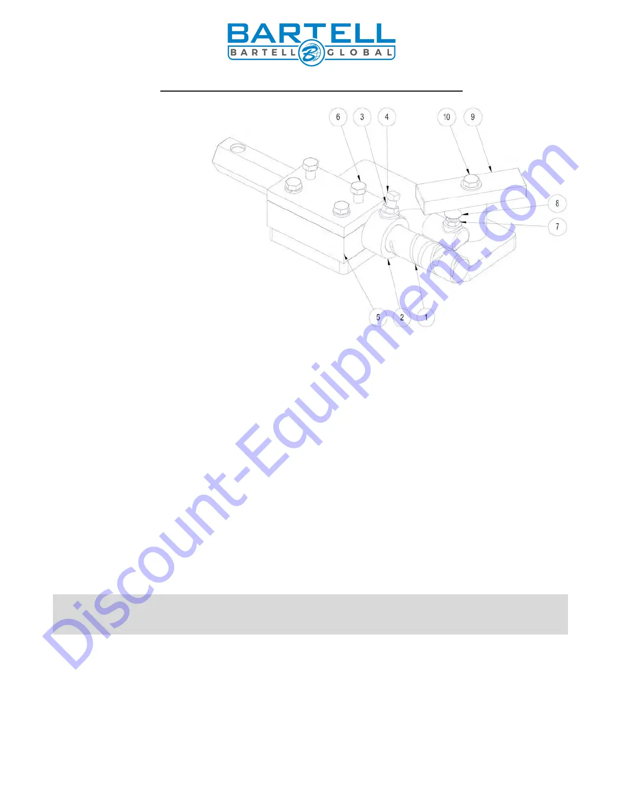
1) 10411 – Trowel arm
2) 10817 – Lift lever
3) 10808 – Jam nut
4) 10809 – Set screw
5) 10824 – Block top
6) 10507 – Bolt
7) 10816 – Ja
m nut
8) 10815 – Carriage bolt
9) 10832 – Adjustment bar
10) 10507 – Bolt
Part #20801
The trowel arm adjustment fixture (20801) is reversible. By rotating the arm clamping
fixture and the ring bolt, both left hand and right hand trowel arms may be adjusted. Before
attempting adjustment, determine whether the trowel arm is right handed or left handed. When
adjusting left hand trowel arms use the side of the fixture marked “L”. When adjusting right hand
trowels arms use the opposite side.
ADJUSTMENT PROCEDURE
1. Remove all trowel arm assemblies (1 & 2 arm and attached lift lever) from spider plate.
2. Remove lift lever (2) from trowel arm (1) by first loosening jam nut (3) then square head
screw (4). If upon inspection (method left to discretion of serviceman) any trowel arm (1)
is found to be in a bent condition, it must either be brought back to its original straight
condition (method left to the serviceman’s discretion) or replaced with new part.
3. Replace lift levers (2) on new or straightened arms (1) by reversing procedure described
above.
4. Place trowel arm assembly (1 and 2) in fixture (5) with lift lever (2) butting up against
fixture. Secure in place with bolts (6).
5. Loosen locknut (7) and screw carriage bolt (8) down to full depth allowable. This will
provide for ample clearance to swing adjustment bar (9) over head of carriage bolt.
Adjustment bar (9) is stamped for appropriate size of machine. Swing appropriate side
directly over carriage bolt (8) and secure in place with bolt (10).