Page 6 of 61 OM1800/26
List of Figures
Figure 1: Grad-01-1000L identification label 8
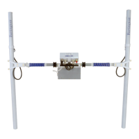
Figure 2: Grad601-2 dual sensor gradiometer arrangement with harness 9
Figure 3: Grad601-1 single sensor gradiometer arrangement 9
Figure 4a: BC601 battery cassette & charger 11
Figure 4b: BC601 battery cassette charging input socket and red LED 12
Figure 4c: BC601 battery cassette 5A fuse, and spare 12
Figure 5: Gradiometer clamp showing Grad-01-1000L cable 13
Figure 6: Heading direction label on Grad-01-1000L connector junction block 13
Figure 7a: DL601 Data Logger underside 14
Figure 7b: DL601 Data Logger connections guide 15
Figure 8: Grad601-2 dual sensor gradiometer carrying harness 16
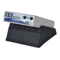
Figure 9: DL601 Data Logger control panel 16
Figure 10: Parallel traverse pattern 30
Figure 11: Zigzag traverse pattern 30
Figure 12: Possible starting points for first traverse 32
Figure 13: First traverse direction when plotted 32
Figure 14: Measurement points on a series of Grids 33
Figure 15: Single sensor operation with trapeze (1m traverses) 34
Figure 16: Dual sensor operation with trapeze (1m traverses) 35
Figure 17: Dual sensor parallel survey at 2 lines/m (dimensions in metres) 37
Figure 18: Dual sensor zigzag survey at 2 lines/m (dimensions in metres) 37
Figure 19: Dual sensor parallel survey at 4 lines/m (dimensions in metres) 38
Figure 20: Dual sensor zigzag survey at 4 lines/m (dimensions in metres) 39
Figure 21: Dual sensor tape marking for 1, 2, & 4 lines/m 40