Completeness check of the product
Before installation of the outdoor panel, it is necessary to check that
it is complete and all components are available.
Outdoor panel kit includes:
Outdoor panel
Manual
Flush mount bracket
Set of wires with connectors for connection of power supply,
lock, and additional modules
A set of cups
Set of screws with a wrench
1 pc
1 pc
1 pc
1 pc
1 pc
1 pc
After verifying the device's completeness, you can switch to the outdoor panel
connection.
For connection you will need:
Electrical connection
An Ethernet UTP CAT5 or higher cable connected to a PoE network switch
or regular switch/router.
Cable length recommendations
The maximum length of the UTP CAT5 cable segment should not exceed 100 meters,
according to the IEEE 802.3 standard.
Power supply at +12 V, 2 amps.
Connection scheme of electromagnetic lock using
uninterruptible power supply UPS-DP/S
1 2 3
+12V GND Lock
+
-
Power
+12 V
Opening
lock time
adjustment
Exit
button
Less
More
N.C.
N.O.
GND
Contact
Fire alarm
input
Switching
contact type:
normally open
or normally closed
1. +12V
2. Ground
3. Lock
4. COM
5. N.C./N.O.
6. Unused
Output to connect
electromechanical lock
LAN
Power
Electromagnetic Lock
SH-45
Door Sensor
SH-42
(optional)
Exit Button
GND
+12V
1 2 3
NC COM
Relay outputs to lock
4 5
NC NO
Wiegand output
1 2 3
+5V D0
4
GND D1
RS485
1 2 3
+12V 485+
4
GND 485-
Exit Button/Door Sensor
1 2 3
Exit Din
4
GND DS
RS232 (Option)
Green
RX
Black White
GND TX
COM
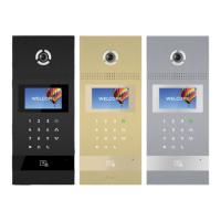
EAN: 5060514912829 (BLACK)
EAN: 5060514912843 (GOLD)
EAN: 5060514912836 (SILVER)