• Avoid an operation near:
- strongmagneticorelectromagneticelds
- transmitter aerials or HF generators
This may falsify the measuring value.
• Do not switch the measuring instrument on immediately after it has been taken
from a cold to a warm environment. Condensation water that forms might destroy
your device. Leave the device switched off and wait until it has reached room
temperature.
• Consult an expert when in doubt about operation, safety or connection of the
device.
• Maintenance,modications and repairsareto be performedexclusively by an
expertorataqualiedshop.
• If you have questions which remain unanswered by these operating instructions,
contact our technical support service or other technical personnel.
b) (Rechargeable) batteries
• Correct polarity must be observed while inserting the (rechargeable) batteries.
• (Rechargeable) batteries should be removed from the device if it is not used
for a long period of time to avoid damage through leaking. Leaking or damaged
(rechargeable) batteries might cause acid burns when in contact with skin,
therefore use suitable protective gloves to handle corrupted (rechargeable)
batteries.
• (Rechargeable) batteries must be kept out of reach of children. Do not leave
(rechargeable) batteries lying around, as there is risk, that children or pets swallow
them.
• All (rechargeable) batteries should be replaced at the same time. Mixing old and
new (rechargeable) batteries in the device can lead to (rechargeable) battery
leakage and device damage.
• (Rechargeable) batteries must not be dismantled, short-circuited or thrown into
re.Neverrechargenon-rechargeablebatteries.Thereisariskofexplosion!
Initial operation
The batteries are already inserted in the DMM upon delivery.
Rotary switch
The individual measuring functions can be set via the rotary switch. If the rotary switch is set
to “OFF”, the measuring device is switched off. Always turn the measuring device off when it
is not in use.
Measuring
Do not exceed the maximum permitted input values. Do not contact circuits or parts
of circuits if there could be voltages higher than 25 V ACrms or 35 V DC present
within them. Mortal danger! Before measuring, check the connected measuring
cable for damage such as, for example, cuts, cracks or squeezing. Defective
measuring cables must no longer be used. Mortal danger!
a) Voltage measuring “V”
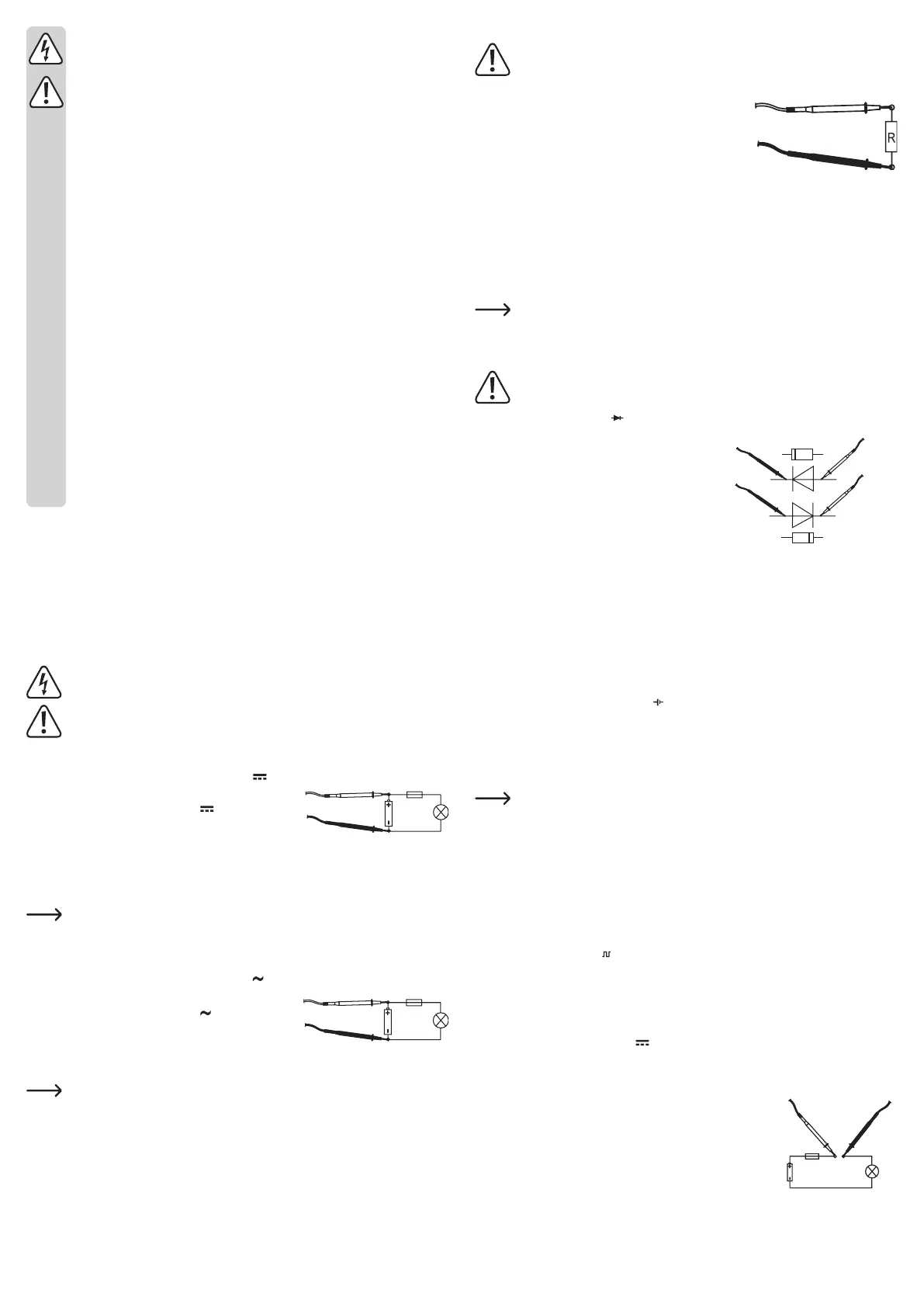
Proceed as follows to measure DC voltages (V ):
• Turn the DMM on on the rotary switch and select the right
measuring range for your voltage “V ”
• Now connect the two test prods to the object to be
measured (battery, circuit etc.). The red measuring tip
indicates the positive pole, the black measuring tip the negative pole.
• The polarity of the respective measuring value is indicated on the together with the current
measuring value.
As soon as a minus “-” appears for the direct voltage in front of the measuring value,
the measured voltage is negative (or the measuring tips have been mixed up).
• Afteryounishtesting,alwaysswitchthemeasuringdeviceoff.Turntherotaryswitchto
“OFF”.
Proceed as follows to measure AC voltages (V ):
• Turn the DMM on on the rotary switch and select the right
measuring range for your voltage “V ”.
• Now connect the two measuring prods to the object to be
measured (generator, switching etc.).
• The measuring value is indicated on the display
The voltage range “V DC/AC” shows an input resistance of >1 MOhm.
• Afteryounishtesting,alwaysswitchthemeasuringdeviceoff.Turntherotaryswitchto
“OFF”.
b) Resistance measuring
Make sure that all the circuit parts, switches and components and other objects of
measurement are disconnected from the voltage at all times.
Proceed as follows to measure the resistance:
• Turn the DMM on on the rotary switch and select the right
measuringrangeforyourvoltage“Ω”.
• Check the measuring leads for continuity by connecting
both measuring prods to one another. After that the
resistance value must be approximately 3 Ohm.
• Now connect the measuring prods to the object to be measured. As long as the object to be
measured is not high-resistive or interrupted, the measured value will be indicated on the
display.
• Assoonas“1”(=overow)appearsonthedisplay,youhaveexceededthemeasuringrange
or the measuring circuit has been interrupted. Switch to the next higher measuring range.
• Afteryounishtesting,alwaysswitchthemeasuringdeviceoff.Turntherotaryswitchto
“OFF”.
If you carry out a resistance measurement, make sure that the measuring points
which you contact with the test prods are free from dirt, oil, solderable lacquer or the
like. An incorrect measurement may result under such circumstances.
c) Diode test
Make sure that all the circuit parts, switches and components and other objects of
measurement are disconnected from the voltage at all times.
Select the measuring range
• Check the measuring leads for continuity by
connecting both measuring prods to one another.
After that the value must be approx. 003.
• Now connect the two measuring prods with the
object to be measured (diode).
• The display shows the continuity voltage in Millivolt
(mV). Usual voltage values: silicon diode ca. 700
mV, germanium diode ca. 250 mV. If “1” is indicated,
the diode is measured in reverse direction or the
diode is faulty (interruption).
• Afteryounishtesting,alwaysswitchthemeasuringdeviceoff.Turntherotaryswitchto
“OFF”.
d) Battery test
With the two measuring ranges, you can test all batteries and accumulators with a nominal
voltage of 9 V/1.5 V or 1.2 V. The cells are slightly charged during testing, which corresponds
to actual operation.
Select the respective measuring range .
For 1.2 V accumulators, select the 1.5 V range.
• Connect the red measuring tip with the positive pole and the black measuring tip with the
negative pole.
• The contact voltage of the battery/accumulator is indicated on the display.
With new batteries or completely charged accumulators, the contact voltage is
slightly higher than the stated nominal voltage.
• Afteryounishtesting,alwaysswitchthemeasuringdeviceoff.Turntherotaryswitchto
“OFF”.
e) Rectangular signal generator
In this range, the DMM works as a rectangular generator for testing audio switching or similar.
In this measuring range, the measuring tips carry a signal of 60±10 Hertz and an amplitude
of 3 Vpp.
Do not short-circuit the measuring cables in this measuring range.
Select the measuring range .
• Connect the two measuring tips with the measuring object (red = signal, black = reference
mass).
• Afteryounishtesting,alwaysswitchthemeasuringdeviceoff.Turntherotaryswitchto
“OFF”.
f) Direct current measuring A
Current measuring is possible in three ranges from 0 to 200 mA. All current measuring ranges
are provided with fuses and thus protected against overload.
Proceed as follows to measure DC voltages:
• Ifyouwanttomeasurecurrents up to max.2000 μA,setthe
rotaryswitchtotheposition“2000μA”orthematchingmeasuring
range.
• Now connect the two test prods in series with the object to be
measured (battery, circuit etc.); the display indicates the polarity
together with the currently measured value.
 Loading...